


Rahne Eric, MSc in Electrical Engineering, founder of PIM Professional Industrial Measurement Technology Ltd., vibration diagnostics expert
More and more companies recognize that through vibration diagnostic condition monitoring and tracking of their rotating machinery, maintenance can be efficiently performed, maintenance costs reduced, and unexpected machine downtimes become less frequent (or even completely eliminated). In many cases, external specialist companies are hired for regular vibration analysis of the machinery fleet, but due to the high costs, there is often a need for in-house measurements or diagnostics within the company. Suitable instruments for this purpose are available from many companies. However, regardless of the differences in capabilities and prices, all portable instruments have one thing in common: machine vibrations must be "sensed" with the vibration sensor attached to the instrument. As simple as it may seem, inexperienced operators often make mistakes related to this aspect, which not only make the measurement results inaccurate but can also render them completely questionable. Let's see what this is all about:
Naturally, every mechanical vibration is strongest at its source. The transfer of vibration energy occurs with more or less strong damping in any material (e.g., steel has weak damping, while rubber strongly absorbs vibrations). The higher the frequency of the vibration, the stronger its damping. As a result, low-frequency vibrations can be detected at greater distances from the source, but the detection range of high-frequency vibrations (several kHz, e.g., bearing vibrations) is very limited. In addition to the mentioned damping, it should also be considered that additional vibration energy loss occurs when vibration is transferred from one body to another (in our case: machine component). The closer two elements are connected, the more vigorously the vibration energy is transferred. Elements not in contact with each other do not follow each other's vibrations. Furthermore, complicating matters is the fact that small elements generating high-frequency vibrations (e.g., bearing components) have a small amount of motion energy that can excite vibrations in larger bodies. Therefore, the following basic rule must be followed: Measure as close to the vibration source as possible! In the case of rotating machinery, measurements should be taken on the bearing housings, as vibrations originating from the rotating components are transferred here, and vibrations resulting from bearing faults (high frequency) can only be measured here! Never measure on loose casings or separate - not in close contact - machine elements if you are interested in vibrations related to the rotating parts of the machine! (Measurements on these mentioned elements should only be performed if there is a suspicion that they may resonate with one of the machine's excitations.)
It matters what frequency range of vibrations we are interested in. For machine condition monitoring, the frequency range recommended in ISO 10816 is most commonly used, where vibrations are measured between 10 Hz and 1 kHz (scaled in velocity effective value). For machines rotating at 3000 revolutions per minute or faster, the frequency range should be set between 10 Hz and 2 ... 3 kHz, while for slow machines (a few hundred revolutions per minute), vibrations should be measured from 2 Hz. Therefore, the measurement task and the conditions to be considered for the measurement vary depending on the machine's speed. Typical industrial machines (1500 or 3000 revolutions per minute) can be accurately measured with most instruments' "standard" sensors - mostly ICP-type (with built-in charge amplifier) piezoelectric vibration accelerometers - provided that the sensor is properly attached to the object being measured. (More on this later.) Electrodynamically sensitive vibration velocity sensors are equally suitable, and in the case of slower rotating machines, they are often even better than piezoelectric sensors: consider that in piezoelectric sensors, the charge is generated by the force acting on the piezoelectric crystal due to the seismic mass built into the sensor, which is then amplified and considered proportional to the vibration acceleration. At slow speeds - although there may be significant displacement or velocity - there is hardly any acceleration, so the forces acting on the piezoelectric crystal do not change, and therefore, there is no charge or signal. The smallest vibration frequency that can be measured by piezoelectric sensors used for machine vibration measurement is around 1 ... 2 Hz (usually there is already a 3 dB damping at 0.3 Hz). However, for faster rotating machines, piezoelectric sensors are almost exclusively suitable for measuring higher frequency vibrations. It is not uncommon for their measurement frequency range to extend up to 15 ... 30 kHz. However, when it comes to the measurability of high-frequency vibrations, it must be taken into account that these can be well followed only by elements with as low weight as possible and with higher natural frequencies. This naturally applies to the sensor required for the measurement as well. If the sensor is not screwed in place, for measuring higher frequency vibrations, a sensor with as low weight as possible should be used. If a magnetic base is used, it should also be as light as possible. (Unfortunately, this reduces the magnetic holding force, which is particularly disadvantageous.) The most significant challenge, however, is the transfer of vibrations from the surface being measured to the sensor: the mechanical coupling of the sensor decisively influences the measurement in the high-frequency range!
This is indeed the most delicate issue! The sensing direction of sensors almost always coincides with their central axis. To ensure correct measurements, it is essential that the sensor closely follows the motion of the measurement point (i.e., the surface of the machine element) in this direction. Depending on the quality of vibration tracking, we may need to expect different measurement results! What is the reason for this? Naturally, the fact that losses occur during vibration transmission also applies to the sensor - the higher the frequency of the vibration, the more difficult it is for the sensor to follow it. The detectability of high-frequency vibrations depends primarily on the type of connection established between the sensor and the measuring surface. The relationships are shown in the following graph:
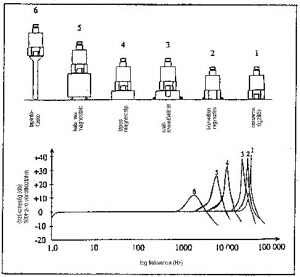
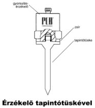
The frequency input dependence Many instruments come with a sensor probe that allows measurements at hard-to-reach - unsuitable for magnetic mounting - measuring points. However, high-frequency vibrations cannot be measured accurately or not at all with this method. The sensor only follows the vibrations that are transmitted through manual touch pressure. This can never be more than 2 ... 3 kHz! It is completely wrong to try to measure vibrations of 5 kHz or higher with a manual touch probe or even mechanically integrated sensor with the instrument. These vibrations will not be detected by the sensor, but the sensor's own frequency or the resonant frequency of the vibrating touch probe and instrument components will affect our measurement! To check the accuracy of the measurement with the probe, temporarily increase the touch pressure. If the readable value changes, we need to check the contact created with the measurement point (paint, loose element ...). If this does not help, always use a holding magnet or mount the sensor directly onto the machine with a threaded stud.
In practice, the use of magnetic mounting bases (holding magnets) has proven to be a general solution, as they provide consistent measurement conditions even for repeated measurements, allow for quick work, and the operator does not have to hold the sensor on the measuring point during data collection. The magnets supplied by sensor and instrument manufacturers - assuming correct handling - can provide the necessary holding force for industrial (non-sterile laboratory) conditions for years to ensure a strong connection between the sensor and the measuring surface. However, do not forget that in order to transmit high frequencies, all contaminants and thick paint layers must be removed! These act as mechanical filters regardless of the strength of the applied magnet.
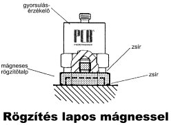
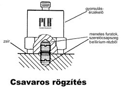
It is not surprising that even when using holding magnets, measurements can only be made in a very limited frequency range, as only the force of the holding magnet ensures the transmission of vibrations. It is disadvantageous that in order to achieve greater adhesion, a larger magnet should be used, but the magnet and the sensor act as one body, and as the weight increases, they become less willing to follow high-frequency vibrations. In general, it can be said that with the use of a proportional size magnet and ensuring a proper measuring surface (flat, clean, unpainted), measurements can be made up to 8 ... 10 kHz. If you want to measure vibrations beyond this frequency limit, you have to use completely different mounting technologies. If you were to glue a washer to the surface to be measured and screw the sensor onto it, with proper adhesive you can measure up to 20 kHz. The measurable frequency range expands to about 30 kHz if you opt for direct bonding of the sensor. (Of course, appropriate high-frequency sensors should be used up to these frequencies.) If you want to measure up to 40 kHz, only one solution is possible: mount the sensor directly onto the measuring surface (flat, clean, unpainted) and assist the vibration transmission by placing wax between the sensor and the measuring surface.
It should be noted that in some cases, additional problems may need to be addressed. On the one hand, the weight of the sensor (and the probe or the holding magnet) can affect the measured value. A good rule of thumb is to accept measurement results with caution if they were taken on machine elements that are 10 times lighter than the total weight of the sensor (including the magnet or probe). On the other hand - as can be seen from the frequency input graph mentioned earlier - there is a so-called coupling resonance at the upper frequency limit of each mounting technology. This is why in the case of measurements with a probe, resonant amplification of vibrations around approximately 3 kHz may occur, and in the case of magnetic mounting, around roughly 10 kHz. The consequence of this is reflected in completely unrealistic measurement results. We hope that our article has provided a physical explanation for those cases where "strange" values are encountered during vibration measurements. It is advisable to choose the sensor coupling as described above and implement it with due care. Believe that our measurement depends much more on this than on the capabilities of the sensor or the instrument! (For example, even if an instrument measures up to 20 or even 40 kHz, if vibrations are detected with a magnet or - in the worst case - with a probe, it is futile!) PIM Professional Industrial Measurement Technology Ltd. H-1221 Budapest, Tanító u. 19/A Tel.: (1) 424-00-99 Fax: (1) 424-00-97 e-mail: pim@pim-kft.hu web: www.pim-kft.hu www.termokamera.hu www.gepszakerto.hu
The content of this publication is protected by copyright, and its (even partial) use, electronic or printed republication, is only permitted with the indication of the source and the author's name, as well as with the author's prior written permission. Violation of copyright (Copyright) will have legal consequences.
Copyright © PIM Professzionális Ipari Méréstechnika Kft.
2026 | Minden jog fenntartva
Impresszum | Adatkezelés