


Rahne Eric, B.Sc. in Electrical Engineering, founder of PIM Professional Industrial Measurement Technology Ltd., vibration diagnostic expert
For preventive maintenance of rotating machinery and daily repair work, it is necessary to use a handheld instrument that is easy to operate, provides clear results, and is more reliable, ensuring that interventions are carried out in a timely manner, at the right place and in the right way according to the condition of the machines. Ideally, the measurement procedure should be such that it can be easily performed without vibration diagnostic experience and engineering training. A common method is based on measuring the vibration velocity effective value. Handheld instruments for this purpose measure the vibration velocity effective value (RMS value) in the frequency range from 10 to 1000 Hz or from 10 Hz to 2000 Hz. These ranges cover the most common frequencies typical of mechanical faults and problems in rotating machinery. Examples include unbalance, misalignment of shafts and gears, cavitation, and other vibrations originating from fluid flow. Based on observed correlations between vibration levels and current machine condition or mechanical problems, the user can quickly develop a typical knowledge base for the machines under examination. The interpretation of measured vibration levels is also supported by various vibration level interpretation standards. One such standard is ISO2372 (or ISO 3945), which has been in use for several decades and is generally good for interpreting continuous operation of machines. Of course, in addition to the standard, the measured vibration values can also be interpreted based on more precise rules derived from on-site practical experience.
Naturally, mechanical vibration is strongest where it originates. The transfer of vibration energy through any material occurs with more or less strong damping (e.g., steel has weak damping, while rubber strongly absorbs vibrations). The higher the frequency of vibration, the stronger the damping. As a result, low-frequency vibrations can be detected at greater distances from the source, but the detection range of high-frequency vibrations (several kHz) is very limited.
In addition to the mentioned damping, it should be considered that additional vibration energy loss occurs when vibration is transmitted from one body to another (in our case: machine component). The closer the connection between two elements, the more vigorously the vibration energy is transferred. Elements not in contact with each other do not follow each other's vibrations.
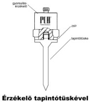
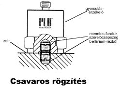
The direction of sensors' detection almost always coincides with their central axis. If the sensor does not have a magnet, then the end of the sensor - the probe or pin - must be pressed firmly against the measuring point surface. The primary goal should be for the sensor to closely follow the movement of the measuring point (i.e., the surface of the machine element). To achieve this, sensors can be placed directly on the measuring surface using a probe, holding magnet, or threaded pin. The best mechanical vibration transmission is achieved with a pin, while the worst transmission is achieved with a probe. (Figures 1, 2, and 3)
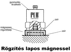
In practice, the use of magnetic mounting bases has proven to be a common solution, as they provide consistent measurement conditions for repeated measurements, are quick to work with, and allow the operator to perform measurements without holding the sensor on the measuring point during data collection. However, it is important to remember that in order to transmit high frequencies, all contaminants and thick paint layers must be removed! These would act as mechanical filters regardless of the strength of the applied magnet.
During routine measurements on horizontal or vertical rotating machinery, follow the three fundamental measurement directions: measure horizontally and vertically perpendicular to the rotating shaft and axially along the shaft. On short and rigid shafts, axial measurement at one bearing is sufficient. For long shafts (e.g., turbines, pressure rollers), it is advisable to measure axially at each bearing. The measurement results can vary significantly!!!
The simplest handheld instruments measure the effective value (RMS value) over the specified measurement frequency range. This effective value is the root mean square of all vibration components. For example, if vibration results from unbalance (4 mm/s), misalignment (2 mm/s), and gear meshing (5 mm/s), then the resultant vibration - i.e., the effective value measured by the device - will be 6.7 mm/s.
Such handheld instruments are recommended for measurements on rotating machinery bearings (or their housings) in accordance with various vibration evaluation standards. For users without experience, it is recommended to base the evaluation of measurement results on the ISO 3945 standard, not without thinking. There are cases that require stricter requirements than the standard and cases that allow higher vibration values than the standard.
Standards generally rely on vibration velocity measurements expressed in mm/s effective value (RMS). The interpretation of measurement results is facilitated by considering the read value as the average speed of the back-and-forth motion. The effective vibration velocity value best reflects the extent of unwanted phenomena, "disruptive energies." These phenomena cause wear and material fatigue in the machine structure wherever they are measurable.
The ISO 3945 standard classifies machines into groups and distinguishes between flexibly and rigidly mounted machines. (The latter corresponds to the classification based on the relationship between the machines' resonance frequencies and operating speeds. For example, a machine mounted with rubber pads or springs - thus flexibly - often exhibits resonances at low speeds. The machine already undergoes significant vibrations at very low speeds. If the speed exceeds these critical resonance frequencies, the vibration level decreases. In the case of a rigidly mounted machine, this does not occur.
Modern machines operate at high speeds, equipped with relatively flexible bearings, peripherals, and foundations. Therefore, these can be treated as flexibly mounted even if they are not fixed with rubber pads or springs. In these cases, the ISO 3945 standard allows slightly higher vibration levels compared to rigid mounting.
By using standards, it is very easy to determine whether certain machines can be operated further or not. Accept it as a basic rule that for any machine showing vibrations greater than 3mm/s effective value (this includes the most common types of machines: e.g., electric motors, pumps, fans, generators), the cause of the vibration must be identified. Do not continue operating a machine vibrating more than 7mm/s unless you are certain that the machine can be operated for a long time without increasing damage, as the endurance of machines varies significantly.
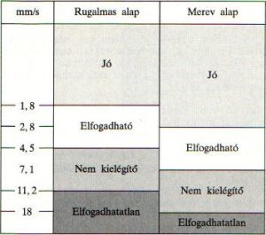
The following section is based on the threshold values for flexible machines according to the old ISO3945 standard, providing a simplified explanation of vibration levels. This list can be used as an initial approach when assessing a machine that has been newly commissioned or has been in operation for a short period.
0 … 3 Small vibrations. No or very slight bearing load. Mostly low noise level.
3 … 7 Noticeable vibration levels often concentrate on a specific component or machine direction. Noticeable bearing load. Sealing problems in pumps, etc. Increased noise level. It is recommended to identify the cause. Plan the intervention at the next scheduled shutdown. Supervise the machine and measure the vibration level at shorter intervals to detect deterioration as soon as possible. Compare vibration with other operational parameters.
7 … 18 Large vibrations. Bearings are hot. Bearing overload results in frequent replacements. Seals are poor, various leaks are possible. Shafts and foundations break. High noise level. Plan immediate intervention and do everything to identify the cause. The equipment wears out very quickly.
18 … Very strong vibrations and very loud noise. This is not compatible with safe machine operation. Stop the machine if the costs of stopping operation can be justified technically or economically. There is no known machine that could withstand this vibration level without internal or external damage. Minimize all operating times to an absolute minimum.
(The table is provided in mm/s units. The above vibration level threshold is not applicable to reciprocating machines (e.g., compressors, internal combustion engines) and machines operating with constant mechanical "friction.")
A vibration level of 4.5 mm/s has proven to be an important limit for mechanically sealed pumps. Above this vibration level, the load on mechanical seals increases, leading to accelerated failure.
The most common handheld instruments measure the vibration velocity effective value in the frequency range from 10 to 1000 Hz or up to 2000 Hz. These ranges cover the most common frequencies typical for mechanical problems in rotating machines. Imbalance, mechanical looseness, resonance, and misalignment of shafts and gears are clearly noticeable. However, there is no information on which of these is present or dominant, as we do not have frequency or phase angle data. Nevertheless, there are some methods to better define the fault indicated by high vibration levels. These will be explained in more detail below: a) Imbalance Since the vibration level does not indicate whether the dominant vibration component in the effective value comes from imbalance producing vibrations at the rotational frequency, this can only be examined with further measurements: for example, try balancing using two- or three-point balancing methods, or investigate the machine for other possible sources of faults, and by exclusion, the presence of imbalance can be inferred. If there are experiences with the machine, perhaps a couple of verification measurements can decide the question. (e.g., fans transporting contaminated, dusty, or process gases tend to become imbalanced over time rather than experiencing an unknown resonance. Loose elements can also occur over time. Therefore, imbalance cannot be determined from a single vibration level data point!) Imbalance is characterized by producing radial vibrations that increase quadratically with increasing speed. Axial vibrations, on the other hand, practically do not occur. b) Resonances In every rotating machine, natural excitations are present continuously, even if only to a very small extent (e.g., imbalance at the rotational speed, single-axis error at twice the rotational speed, etc.). If one of these has a frequency similar to or the same as the resonance frequency of a machine component, depending on the stiffness and mass of the component, the vibration in this machine part intensifies, causing the component to resonate. A significantly higher vibration level appears than when the resonance and excitation frequencies are different. The fundamental resonance frequency of every machine is the critical speed of the rotating shaft, resulting from the shaft's stiffness and mass. However, every other machine component also has resonance frequencies, including auxiliary units and structural elements. To detect a resonance, measure the vibration level on the bearing housings in all measurement directions. If one of these is three times larger than the others, we can be almost certain that a resonance is present. Resonance amplifies the mechanical force and thus generates strong vibrations in this direction.
If changing the machine's speed (if possible) results in significant changes in vibration levels, this should always be interpreted as a sign of resonance. Furthermore, this phenomenon provides an opportunity to determine the resonance frequency, from which conclusions can be drawn about the resonating machine component or group of components. (The resonance frequency is the speed at which the vibration is strongest.) c) Loose machine elements, loose fastening For example, by performing vibration measurements on both sides of a bolted connection, it is possible to identify loose machine elements within the connection. Two tightly connected machine elements should exhibit the same vibration level on both sides of the connection. And of course, bolts fastened to the foundation should show the same vibration level as the foundation, provided they have not loosened. PIM Professional Industrial Measurement Technology Ltd. H-1221 Budapest, Tanító u. 19/A Tel.: (1) 424-00-99 Fax: (1) 424-00-97 e-mail: pim@pim-kft.hu web: www.pim-kft.hu www.termokamera.hu www.gepszakerto.huThe content of this publication is protected by copyright, and its (even partial) use, electronic or printed re-publication is only permitted with the indication of the source and author's name, as well as with the author's prior written permission. Violation of copyright (Copyright) will have legal consequences.
Copyright © PIM Professzionális Ipari Méréstechnika Kft.
2026 | Minden jog fenntartva
Impresszum | Adatkezelés