


Eric Rahne, B.Sc. in Electrical Engineering, Level 3 Accredited Thermography Expert (PIM Ltd.)
Thermography can be found in almost every profession nowadays. We are currently experiencing the most rapid spread of this contactless temperature measurement method, but also its most severe professional devaluation. Some thermal camera manufacturers and distributors have stooped to the level of labeling 80x60 pixel smartphone accessories without radiometric capabilities (and similar products) as professional thermal cameras (as if we were upgrading a VGA webcam to a professional video camera). Furthermore, it is disheartening that anyone who buys such a cheap device titles themselves as a thermographer without any professional training, often without even basic knowledge (and consideration) of physics and metrology! In our upcoming series of articles, we aim to provide insights into the incredible versatility and theoretical as well as practical limitations of thermography, drawing from Rahne Eric's 650-page specialized book titled "Thermography - Theory and Practical Metrology". The first parts will focus on the assessment of electrical distribution, switching, and control cabinets.
Taking thermal images, i.e., thermography, is an extremely versatile measurement method, while the user-friendly operation of modern thermal cameras can be compared to common digital video cameras. However, this simplicity should not deceive anyone: to capture correct thermal images from a measurement perspective, appropriate theoretical, professional knowledge, experience, and thorough measurement preparation are necessary. Since we have already covered the theoretical basics of thermographic measurements in previous issues of VL, we will now detail the most important measurement requirements and practical knowledge for thermographic inspection of electrical equipment. Within this, we will also highlight the impact of some common thermal camera operator errors on the accuracy and credibility of measurements.
As wide as the possibilities are with the preferably regular application of thermography in organizing the maintenance of electrical equipment, just as many difficulties arise during the implementation of measurements. Below, we present some significant problems, along with advice on minimizing the extent of measurement errors. The biggest problem arises from the object of measurement itself - precisely from its material. One common fault in electrical equipment is caused by the improper conductivity of contacts based on screw, spring, or crimped connections. Although any increased transient resistance leads to proportional contact heating, due to the small emissivity of metallic, mostly polished surfaces, the heat radiation emitted is minimal. Therefore, while it is possible to detect contact heating with thermographic tools, precise measurement is almost impossible. Similarly challenging is measuring on rail systems without insulation. Here, the metallic surface of the object being measured causes a measurement error of unforeseeable magnitude. The low emissivity of the surface of objects with non-visible properties results in a high reflectivity factor, so our measurement activities must be organized in a way that minimizes this measurement error. It is important to pay attention to this during the measurement itself, as post-correction is practically impossible due to the heterogeneous industrial environment in the direction of the reflected heat radiation source. Our first task is to strive for a measurement setup with as homogeneous environmental temperature as possible. This requires a measurement setup where there are no strong heat sources operating in the direction of the radiation reflected by the object during the measurement, such as a heater, radiant hall heating, high-temperature technology, or other point- or line-shaped interfering radiation sources. Anything that cannot be temporarily shut down should be eliminated using a different measurement or observation angle. If this does not provide a solution, then cover it with a screen or other shading surface, ensuring it does not reach the interfering heat radiation source and does not pose a fire hazard. The overzealousness of local electricians often accompanying thermographers falls into the same category. While one switchgear row is being surveyed, they already open the doors of the switchgear row behind the person conducting the measurement. From this point on, instead of the almost homogeneous reflective temperature provided by the doors of the switchgear row, the inhomogeneous, location-dependent varying heat radiation of the electrical elements in the cabinets will be reflected on the measurement object! Now comes the coup de grâce in the reflection problem. Both the person conducting the measurement and their companion, as well as the observers of the measurement, all become interfering radiation sources causing reflective heat effects! We cannot remove ourselves from the field of view, but we can remove the companion and the observers. We need to come up with something to eliminate the heat radiation caused by our bodies. The solution is to perform the measurement on the object surfaces at an angle of 70 ... 80°, rather than at a 90° angle, to avoid reflection of other interfering heat sources. If no interfering heat source is reflected during the measurement from this angle, the task is already solved.
However, if we discover heat effects on the thermal image that are suspicious of reflection, change our measurement position and repeat the thermographic capture from a different observation angle. If the location of the suspected reflection heat effect changes, then it is indeed a reflection. In this case, we need to find a "third" observation direction to prevent the reflection from affecting our measurement. If this is impossible, make a note of the reflection for documentation during the measurement. If changing our position and observation angle does not alter the depiction of the heat effect on the thermal image, then it is a real - object-related - heat effect.
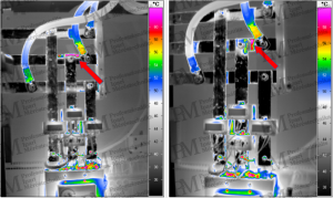
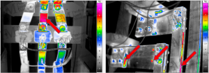
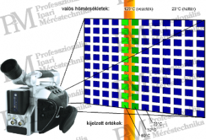
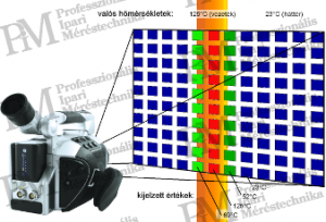
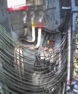
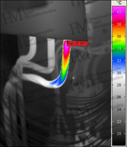
As proven by Figures 3-4, the location marked with the red arrow shows reflection, not object-related heat. Due to the mostly polished surfaces of the contacts, in addition to misleading reflections, the poor detectability of real object temperatures causes problems. Fortunately, there are usually some labeled, painted, or insulated surfaces that also heat up due to the heat conductivity of the electrical conductors through the heating of the fault location. Existing holes in busbars can also be helpful. If they have a depth at least four times their diameter, then due to the multiple reflections occurring in them, we can measure radiation corresponding to nearly 100% emissivity when measuring into them at an angle. This applies to through-holes or threaded holes, as well as assembly gaps between two busbars. (Figures 5-6)
Another underestimated problem is related to the geometrical resolution of thermographic measuring equipment. Due to the importance of this topic, I consider it necessary to mention it in more detail here. It is often heard about an overview thermographic survey of an entire switchgear with a subsequent detailed fault recording based on the overview thermal image. This sounds like very efficient work, which is true only if the requirement of geometrical resolution is adhered to during the overview image capture. Violating this requirement will leave unnoticed the heat effects indicating problems with smaller wires and contacts. Detailed thermal images would likely not be captured, meaning that the faults would not be detected. In summary: the capture of overview thermographic images with inadequate geometrical resolution is simply not allowed, and there are no exceptions to this rule. The parameter influencing all this (referred to as IFOV = Individual Field Of View or Instantaneous Field Of View in English documentation, translated as "unique sensor angle of view") - the angle of view of a unique sensor (pixel) of the detector matrix - is typically given in mrad (milliradian) units, not in degrees. This greatly facilitates the mandatory pre-calculation related to geometrical resolution (before each thermal image capture). Caution: the data applies to the combination of the thermal camera and the lens, so with different field of view lenses, the same thermal camera will have different geometrical resolutions. (Figure 7)
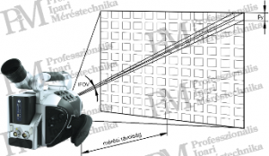
Fortunately, it is quite simple to determine the smallest object dimension measurable from a given distance in milliradian units in the specification of the thermal camera (or its lens) with the geometric resolution (IFOV) value. For example, an IFOV value of 1.5 mrad means that each unique measurement area (measured spot perceived on the object surface) assigned to each pixel at a measurement distance of 1 m is exactly 1.5 mm in size. The equation for the unique "measuring spot" generated at the given distance is: px = py = d ⋅ IFOV where: px, py ... horizontal size of the unique detector measuring spot [mm] d ... measurement distance [m] IFOV ... geometric resolution [mrad] Based on the above, it is known what size the measuring spot belonging to a unique detector is at the given measurement distance. Now it is only necessary to ensure that the measuring spot is entirely located on the object to be measured. If this is not adhered to, the measuring spot may contain not only the radiation from the object surface but also from its background (more precisely, from the closely adjacent or laterally shifted object visible behind it). Since averaging occurs within the measuring spot, due to the temperature of the background (lateral environment), the measurement result may be either lower or higher than the actual temperature of the object. The greater the difference between the temperature of the object and the background (lateral environment), the greater the measurement error will be! Since the position of the sensing area (measuring spot) corresponding to each pixel on the object to be measured is unknown, mathematics can be used for assistance. If the minimum size of the smallest measurable object were twice the size of the unique measuring spot, then one of two closely adjacent such unique measuring spots will always be entirely located on the object. However, since the detector matrix has gaps (necessary for manufacturing technology) and the lens system is not free from imaging errors from a measurement technology perspective, in practice, it has proven useful to multiply the above pixel size by 3 to determine the minimum size of the smallest measurable object. mmin = szmin = d ⋅ IFOV ⋅ 3 formula (2) where: mmin ... vertical size of the smallest measurable object [mm] szmin ... horizontal size of the smallest measurable object [mm] d ... measurement distance [m] IFOV ... geometric resolution [mrad] Based on the equation, for example, with a "standard" lens providing a 2 mrad geometric resolution, from a distance of 5 m, only objects (or object details) with a minimum size of 30 mm can be reliably and correctly detected thermally. To measure smaller objects, either a shorter measurement distance or different optics must be chosen. (Otherwise, the thermal image cannot detect the temperature of small objects/object details that are important for the measurement.) If the aforementioned "standard" lens is replaced with a telephoto lens, for example, assuming a 0.5 mrad geometric resolution, objects with a minimum size of 7.5 mm can be measured from a distance of 5 m.
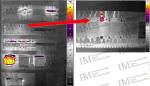
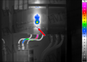
Images 8-9 clearly demonstrate the measurement error and its magnitude in case of inadequate geometric resolution. While in the upper image we observe the actual temperature of a larger diameter cable on our thermal image (displayed maximum value 125°C), in the case of the lower image, we incorrectly perceive the temperature of an equally hot but thinner cable (displayed maximum value 69°C). The next two thermal images support the risk of taking an "overview" image with inadequate geometric resolution with a specific practical example. I believe further explanation is not necessary. Thermal images 10-11 confirm the risk of taking an "overview" image with inadequate geometric resolution with a specific practical example. While in the 10th image, the loose contact is barely noticeable with a temperature of 38°C and does not appear as a fault, in the 11th image, based on the thermal detail image with appropriate geometric resolution, it becomes clear that its actual temperature is above 58°C (measurement error of 20°C)!
Our situation is not simple due to the coverings of electrical installations. Since on plastic materials as thin as half a millimeter, almost no thermal radiation passes through, which would enable the measurement of electrical equipment, it is completely obvious that plastic coverings covering the elements to be measured must be removed before measurement. This applies to covering plates of fuses and miniature circuit breakers as well as to the plexiglass covers inside cabinets. However, what we definitely cannot remove in practice is the completely closed plastic enclosures of modern installations. In fortunate cases, the manufacturer of the installation left a small hole, 3 ... 4 mm in diameter, through which - from an appropriate viewing angle - in case of a fault or poor contact in the installation, the critical temperature inside can be observed. Of course, for fault detection through the hole, it is necessary to choose our maximum measurement distance according to the geometric resolution matching the size of the hole. (See the previously discussed problem.) And if there is no such hole for detecting internal issues in the covering, then we can only rely on good heat conduction of the electrical conductor. The examples shown in images 12-13 are quite reassuring in this regard, as in most cases, the fault in the enclosed equipment or contact can mostly be clearly linked to the temperature of the outgoing conductor, which decreases as it moves away from the device in question.

Finally, here is one more attention-grabbing example regarding the heat effects not visible thermally due to plexiglass coverings for touch protection. In the example, the actual temperature of a loose contact visually seen but thermally undetectable due to covering is 57°C. This would definitely justify maintenance intervention, unlike the seemingly acceptable 41°C value. (Nevertheless, the difference between phases is already sufficient reason for the necessity of inspection and maintenance.)
(To be continued!) Rahne Eric (PIM Ltd.) pim-kft.hu, termokamera.hu
The content of this publication is protected by copyright. Any (even partial) use, electronic or printed re-publication is only permitted with the indication of the source and the author's name, and with the author's prior written permission. Violation of copyright (Copyright) will result in legal consequences.
Copyright © PIM Professzionális Ipari Méréstechnika Kft.
2026 | Minden jog fenntartva
Impresszum | Adatkezelés