


Eric Rahne, B.Sc. in Electrical Engineering, Level 3 Accredited Thermography Expert (PIM Ltd.)
Based on the detection of infrared radiation, the temperature of an object (surface) can only be calculated (based on the thermographic basic equation) with precise knowledge of the emissivity factor, the reflected thermal radiation (ambient temperature), and (in the case of optically transparent bodies for thermal radiation) the background temperature. The lower the emissivity factor of the object (its radiation-emitting capacity), the more corrections need to be made, therefore all parameters must be provided more accurately. From the mentioned relationship, it follows that in some cases the temperature of the object cannot be measured at all:
As an explanation, in both cases, the emissivity value is close to "0", therefore there is almost no radiation available for temperature calculation based on its detection related to the object's temperature. In practice, this fact is of great significance: it must be acknowledged that, for example, thermal insulations with new - nicely polished - aluminum or stainless steel cladding cannot be inspected with thermographic devices. It does not matter what temperature (even extremely hot) the measured surface is, we will always see ("measure") only the temperature of the surrounding objects reflected on it. A similar situation arises when new electrical installations, switchgear cabinets need to be inspected: the temperature of the metallic (polished) rails, connections, joints cannot be determined without contact. (However, oxidized or painted /coated with insulating material/ surfaces can be measured - as they have a high emissivity factor due to their non-metallic, matte nature.)
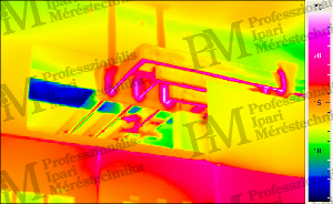
new - polished surface - copper strip - the bottom of the strip appears warmer than the rest, although due to copper's good thermal conductivity there are certainly no differences - the visible heat effect comes from the reflection of warm devices located under the copper strip. If a thermogram contains various material surfaces, pixel-by-pixel emissivity correction may be necessary for accurate temperature calculation. A classic example is the assessment of the thermal load of electronic circuits: there are non-metallic surfaces (ceramic, plastic, varnish) and metallic (copper, tin, nickel, and gold) surfaces. As a solution, the PCB to be inspected is uniformly heated to a temperature sufficiently different from the environment (e.g. to 50°C in a 20°C environment) and the detectable thermal radiation intensity is stored as pixel-by-pixel emissivity factors. The calculation of the thermal image of the circuit put into operation is then carried out using the previously recorded emissivity factor pixel matrix by the software, resulting in the precise determination of the temperature data for each pixel despite the different emissivity factors. Example of pixel-by-pixel correction for different emissivity factors
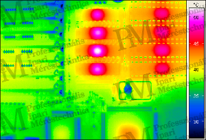
- hot circuit legs appear cold in reality - the cause of incorrect data is the different emissivity values

- seemingly different temperatures are present - the differences are due to different emissivity values

- pixel-by-pixel correction based on the left image - the hot circuit legs appear hot in the thermal image as well
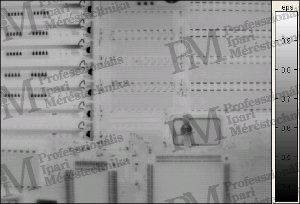
- determination of the average temperature and the emissivity was determined pixel by pixel
This chapter deals in detail with what measurements (with what results) can be carried out using thermographic methods related to electrical equipment and what to pay attention to in order to eliminate measurement errors. Thermographic measurements related to electrical equipment The thermographic condition assessment of electrical equipment is based on the fact that undersized or damaged cables, poor connections (due to their increased transient resistance), and in most cases electrically faulty devices heat up to higher temperatures than usual (permissible). The greatest advantage of thermography is that measurements can be carried out from a safe distance - even on equipment operating at several kV - without affecting the operation of the device under test. Common application areas
![Industrial fuse survey [source: Infratec]](/images/3846/vl2-6.png)
Important Tips
While we explained the meaning of technical parameters characteristic of thermal cameras in the previous section, here we provide the selection criteria for the appropriate measuring device (thermal camera) for specific professional fields. I. For surveying electrical equipment- Wavelength range: long-wave Note: The typical temperature range of electrical equipment is between 0°C and 200°C. These measurements are best performed with a long-wave thermal camera, as bodies emit predominantly long-wave radiation at these temperatures according to Planck's law. - Measurement (calibration) range: at least 0°C ... 150°C or preferably: -20°C ... 250°C Note: The measurement range should be selected based on the expected temperatures of the equipment to be measured. If a thermal camera with a wider calibration range is available at a similar price, choose it for safety. Cameras calibrated from -20 or -40°C provide the best image quality as they have lower noise levels. - Number of pixels: min. 160x120 or 320x240 pixels, better 384x288 pixels Note: With fewer pixels, only very small areas can be captured, for example, with 120x160 pixels, only a part of a switch cabinet /depending on the smallest cable cross-section, only a quarter or eighth/ can be captured in a thermal image. Therefore, such a small camera is suitable for fault detection /especially if it has automatic visual or acoustic alarms for threshold exceedance/, but documenting complete electrical networks or manufacturer equipment is not cost-effective due to the large number of images and necessary image montages. - Geometric resolution: min. 2 mrad, better 1.5 mrad, best 1 mrad Note: Since at least 2 elementary pixels should fall on the smallest object to be measured /the smallest cable cross-section/, the geometric resolution limits how far thermal images can be taken. With a "poor" geometric resolution thermal camera, it may be necessary to take 8-10 images of each switch cabinet to ensure correct measurement of every cable and connection. - Temperature resolution: 120 mK or better: 80 mK When surveying electrical equipment, significant temperature differences can be expected, so temperature resolution is not as critical. - Image acquisition frequency: no restriction Note: The image acquisition frequency of the thermal camera is limited only by the fact that scanning thermal cameras require a camera stand due to their 1-second image acquisition time. With faster matrix cameras, images can be taken "by hand." - Recommended "special" features: selectable color palette, autofocus, built-in digital video camera, or composite imaging (visual and thermal images superimposed).
![Integrated circuit with microscope lens [source: Infratec]](/images/3847/vl2-7-300x209.png)
![PCB with standard lens [source: Infratec]](/images/3848/vl2-8-300x209.png)
II. For microelectronic measurements (processes involving rapid temperature changes)- Wavelength range: long-wave Note: The typical temperature range of electronic devices is between 0°C and 200°C. These measurements are best performed with a long-wave thermal camera, as bodies emit predominantly long-wave radiation at these temperatures according to Planck's law. - Measurement (calibration) range: min. 0°C ... 150°C or better: -20°C ... 250°C Note: The measurement range should be selected based on the expected temperatures of the electronic device to be measured. If a thermal camera with a wider calibration range is available at a similar price, choose it for safety.Of course, the best image quality is provided by cameras calibrated from -20 or -40°C, as they have lower noise levels. - Number of pixels: min. 160x120 or 320x240 pixels, better 384x288 or even 640x480 pixels Note: With fewer pixels, only very small areas can be captured, so with, for example, 120x160 pixels, only one or two integrated circuit areas can be recorded in a thermal image. Therefore, such a small camera is good for troubleshooting /especially if it has automatic visual or acoustic alarm for threshold exceedance/, but measuring and documenting complete boards /electronic panels/ can only be done with a lot of recordings and thermal image montages. - Geometrical resolution: min. 1.5 mrad, better 1 mrad Note: Since it is necessary for at least 2 elementary pixels to fall on the smallest object to be measured /the smallest cross-section circuit leg or printed wire surface/, the geometrical resolution limits how far thermal images can be taken from. A "poor" geometric resolution thermal camera can lead to the need for 8-10 images to be taken of each board for proper assessment of each component and wire. - Temperature resolution: 120 mK or better: 80 mK When measuring electronic devices, significant temperature differences can be expected, so temperature resolution is not as critical. - Image acquisition frequency: > 2 x process frequency Note: This is one of the most critical parameters for thermal cameras in fast processes. Since thermal image capture is considered digital sampling, it is necessary to adhere to the basic pillar of digital signal processing, the Shannon theorem. Accordingly, at least twice as fast sampling /in our case thermal image capture/ must be done as the highest frequency component of the process. For example, if a power electronics system heats and cools at a 50 Hz supply rate, the thermal image acquisition frequency must be higher than 100 Hz. Otherwise, aliasing effect occurs, and due to undersampling, slower processes /changes/ can be observed in the representation of the temperature process over time. - Recommended "special" features: selectable color palette, autofocus, difference image (what changed compared to the reference thermal image), sequence capture, pixel-wise emissivity correction (components used in electronics - copper, ceramic, plastic have very different emissivity factors, manual correction of many small surfaces is almost impossible).
![Inspection of air ducts, connections, and insulators [source: Infratec]](/images/3849/vl2-9-300x209.png)
Survey of electrical overhead lines- Wavelength range: long-wave Note: The temperatures measurable on overhead lines can vary significantly depending on their load. A typical temperature range (in summer, at night) can be 10...150°C. Measuring such temperatures is best done with a long-wave thermal camera because according to Planck's law, bodies emit predominantly long-wave radiation at these temperatures. - Camera type: matrix or scanning (point-and-shoot) Note: In case of faults in overhead lines or insulators, significant temperature differences can be expected, so image homogeneity is not as critical. Both scanning and matrix cameras can provide perfectly evaluable data. - Measurement (calibration) range: -20°C ... 120°C or better: -40°C ... 300°C Note: Since these are outdoor measurements, they must be done at night. Depending on the season, the temperature may drop below -10°C during the measurement, and in such cases, only a thermal camera with a calibration range starting from -20°C can produce acceptable quality images. Cameras calibrated from -40°C provide even better image quality, as they have lower noise levels. Therefore, we recommend the use of thermal cameras calibrated from -20 or -40°C. - Number of pixels: min. 320x240 pixels, better 384x288 pixels Note: With fewer pixels, only very small areas - e.g., with 120x160 pixels, only a single insulator - can be captured in a thermal image. Surveying a section of overhead lines would require a large number of images, which would also be a huge task to process. - Geometrical resolution: min. 0.3 mrad or better 0.2 mrad Note: This is the most critical parameter for surveying overhead lines! To measure the temperature of a 20mm diameter conductor correctly at a height of 30m /at least two elementary pixels must fall on its surface/, a geometrical resolution of 0.3mrad or better is required. Since there is a "gap" between the pixels of matrix cameras, an even stricter condition should be applied /3 pixels must fall on the surface/, therefore, safely accurate measurement can only be guaranteed with 0.2 mrad. - Temperature resolution: 120 mK or better: 80 mK The most common temperature differences are expected at the faults in overhead lines, so temperature resolution is not as critical. - Image acquisition frequency: no restriction for ground-based or vehicle-based image acquisition Note: The image acquisition frequency of the thermal camera is limited only in terms of the 1-second image acquisition time of scanning thermal cameras, requiring the use of a camera stand. For matrix cameras, a stand is also necessary, as otherwise, the conductor or insulator in the distance cannot be "aimed at." - Recommended "special" features: selectable color palette, autofocus, appropriate telephoto lens, real (electro-optical) zoom for scanning cameras, possibly composite imaging (visual and thermal images projected onto each other), camera stabilizer required for recording from a moving vehicle. I am happy to provide professional advice to all interested parties. Rahne Eric (PIM Ltd.) pim-kft.hu, termokamera.hu
The content of the publication is protected by copyright, and its (even partial) use, electronic or printed re-publication is only permitted with the indication of the source and the author's name, and with the author's prior written permission. Violation of copyright (Copyright) will result in legal consequences.
Copyright © PIM Professzionális Ipari Méréstechnika Kft.
2026 | Minden jog fenntartva
Impresszum | Adatkezelés