


Eric Rahne, B.Sc. in Electrical Engineering, Level 3 Accredited Thermography Expert (PIM Ltd.)
The creation of thermal images, i.e., thermography, is an extremely versatile measurement procedure. Operating modern thermal cameras is becoming increasingly similar to using common digital video cameras, and their purchase prices have dropped to a fraction of what they used to be in previous years. It is not surprising, therefore, that electricians are getting closer to this new technology. While in the past only phase testers, then voltage and resistance meters, later multimeters, grounding testers, and even oscilloscopes became everyday tools, it is expected that thermal cameras will also become part of the daily routine of electrical professionals. However, the simplicity mentioned above should not deceive anyone: professional knowledge, proper measurement preparation, and a measuring instrument (thermal camera) that meets the requirements of the task are necessary for creating thermographic images that are correct from a measurement perspective. (Otherwise, instead of measurement results, only uninterpretable "color images" will be produced.) It is a sad experience that several thermal camera distributors and thermal imaging service providers make serious professional mistakes during the creation of thermal images. Therefore, to avoid this, let's start with the physical principles!
Generation of Infrared Radiation (Thermal Radiation) Non-contact temperature measurement and thermography utilize the physical phenomenon that above absolute zero K temperature (-273.15 °C), bodies emit electromagnetic waves, such as radio waves, light, and heat (radiation). Infrared radiation (thermal radiation) is found in the wavelength range between 760 nm and 1 mm in the electromagnetic spectrum. From a technical perspective of temperature measurement, the range up to 20 µm is significant. This range can be divided into the following parts: 0.8 μm...2 μm ultrashort-wave infrared 2 μm...6 μm short-wave infrared 6 μm...20 μm long-wave infrared Therefore, temperature measurement is based only on the electromagnetic waves emitted by the object being measured - infrared radiation. To infer the temperature of an object based on this radiation, the relationship between the object's temperature and the emitted radiation must be considered. This relationship is described by the Planck radiation law, which characterizes the spectral distribution of radiation emitted by an ideal radiator (black body) (see figure below).
![Planck Radiation Law [source: Infratec]](/images/3831/vl1-1.png)
In summary, the hotter a body is, the more radiation it emits, and the shorter the wavelength of the most strongly emitted radiation. It is also noteworthy that long wavelengths are always present (strengthen with increasing temperature), while short wavelengths are emitted only by hot bodies. Properties of Objects to be Measured The so-called black body is the ideal physical model of a radiator that emits 100% of the thermal radiation expected according to the Planck radiation law based on its temperature. However, the radiation capability of real objects falls short of the black body model, and the emissivity factor (ε) is used to account for this difference, describing the object's thermal radiation emission capability compared to that of a black body. The emissivity factor primarily depends on the material (mostly on its surface), as well as on the surface roughness, viewing angle, and wavelength (thus on the object's temperature as well). In the long-wave range, many non-metallic materials are characterized by a high-value, relatively constant emissivity factor over a wide temperature range independent of surface finish. Good examples include human skin, many mineral materials (e.g., concrete, plaster, etc.), and paint based on plastics. The emissivity factor of metals is usually small, highly dependent on surface characteristics, and decreases with increasing wavelength (decreasing temperature). Effect of Measurement Setup and Transmission Medium on Measurement Results In non-contact temperature measurement, the peculiarities arising from the physical fundamentals of this measurement method must be taken into account: firstly, it is an "optical" measurement method, so the measurement object must be visible from the measuring device, and secondly, besides two key elements of the measurement setup, the characteristic state of the measurement path and the possible presence of radiation sources in the foreground or background play a crucial role in the measurement.
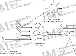
Since the measurement is based on the "remote" detection of infrared radiation emitted by the object, this radiation must pass through some medium from the object being measured to the measuring device, and the behavior (characteristics) of this medium in the infrared range naturally affects the measurement. In most cases, this medium is air, but other materials that transmit infrared waves (such as special measurement windows) also exist. In the case of air, the transmission of infrared radiation is primarily influenced by the water vapor and carbon dioxide it contains.
![Spectral Transmission Factor of Air [source: Infratec]](/images/3833/vl1-3.png)
As shown in the above figure, the transmission properties of air greatly depend on the wavelength. Regions characterized by high transmission losses are adjacent to regions with good transmission capacity (shaded). The latter are also known as atmospheric windows. While the transmission factor in the 8...14 μm range - the long-wave atmospheric window - provides almost perfect transmission even over long distances, in the 3...5 μm range - the short-wave atmospheric window - the atmosphere causes measurable losses even at distances of several tens of meters.
Since in non-contact temperature measurement air is the most common transmission medium, measurements should naturally only be carried out in the wavelength ranges of the aforementioned atmospheric windows (otherwise a non-linear temperature dependence would be obtained). Therefore, instruments sensitive to the 8...14 μm wavelength range – operating utilizing the long-wave atmospheric window – and capable of detecting the 3...5 μm wavelength – measuring in the short-wave atmospheric window – are used for measurements, such as infrared thermometers and thermal cameras. Accordingly, they are named long-wave or short-wave infrared thermometers, or thermal cameras. Infra-red thermometers measuring in the ultra-short wavelength range are less common, and thermal cameras are practically not manufactured in this range. Thus, the spectral measurement range of non-contact temperature measurement instruments typically covers only a part of the total radiation emitted by the object. According to Planck's radiation law, instruments in the short-wave (3...5 μm) range are quite insensitive to relatively low temperatures; however, above 350 °C, the detectability of radiation in the 3...5 μm range is better than in the long-wave (8...14 μm) range. (This is because the maximum radiation has shifted to the short-wave range.) Structure and operation of thermal cameras In recent years, matrix detector thermal cameras have been increasingly used in infrared thermography. The structure of such a camera in many ways resembles a digital camera (or digital video camera), although the individual components are of course quite different.
![Schematic radiation path of a matrix detector (Focal Plane Array = FPA) thermal camera [source: Infratec]](/images/3834/vl1-4.png)
Each pixel of the thermal image is converted into an electrical signal by a unique sensor. The electrical signal is then amplified by a specifically low-noise preamplifier, followed by digitization. The resulting – per-pixel – digital data represents the amount of sensed thermal radiation. To determine the surface temperature of the object, the digital data associated with each pixel must be converted into temperature using the basic thermographic equation (based on, among other things, the emissivity factor, the environmental temperature, and the characteristics of the transmission section), which is performed by a high-performance computer integrated into the thermal camera. However, the computer's task is not only this, as in the case of matrix detectors, the characteristics of individual pixels (unique sensors) can be very similar to their neighboring elements, yet measurably different. Compensating for the lack of similarity requires a significant amount of real-time, calculation-based signal processing (correction), which the internal computer must handle. Therefore, the first thermal cameras made with matrix detectors were recommended without temperature measurement functions. Camera manufacturers only later integrated this technology into the devices, initially with just one – in the center of the image – measuring point, later extending it to all image points (as the performance of computers naturally improved). Most general-purpose matrix detector cameras are made with the relatively new Quantum Well (thermal resistance or bolometer) sensor technology, which enables the production of high-resolution sensors with high thermal and geometrical resolution within the long-wave range. In some cases, the not overly strict requirements for the reaction time of individual elements of matrix detectors allow for the use of detectors without cooling. However, due to radiation physics reasons, achieving the expected high thermal resolution at low temperatures can only be imagined in the long-wave range with uncooled equipment. Geometrical resolution of thermal cameras Geometrical resolution significantly influences the image quality of a thermal camera, as well as the accuracy of measurements, and even the applicability of the thermal camera for certain tasks. The so-called IFOV parameter (Instantaneous Field of View) specifies the viewing angle that maps to a unique sensor (pixel). For example, a value of 1.5 mrad indicates that each measurement point assigned to a pixel – projected onto the object – has a diameter of 1.5 mm at a distance of 1 m, a projected surface with a diameter of 3 mm at a distance of 2 m, and so on. (This should be imagined as the beam of a flashlight, which covers an increasingly larger circular surface depending on the distance.)
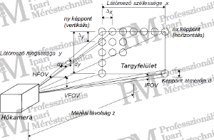
It is important that the object being measured is at least 3 times (but at least 2 times) larger than the unique measuring surface projected at the given distance; otherwise, the measurement spot may contain not only the surface of the object but also its background. Since averaging occurs within the measurement spot, due to the background temperature, the measurement result can be either lower or higher than the actual temperature of the object. The greater the difference between the temperature of the object and the background, the greater the error in the measurement! Naturally, the above rule applies not only to small objects (such as thin wires, filaments, etc.) but also when measuring large objects (such as large cross-section cables, openings, etc.). Obviously, different dimensions are involved: in the case of small objects, we are talking about measuring surfaces of millimeter size, which can be measured from distances of up to several tens of centimeters based on the geometric resolution of the applied thermal camera and optics; in the case of large objects, we are talking about measuring surfaces of centimeter size that are sensed from distances of several meters (up to 10 meters). In all cases, the use of equipment that allows compliance with the rule is necessary! Since the geometric resolution always refers only to the optics currently in use, it is essential to check whether the optics mounted on the thermal camera meet the desired field of view and focal length. While some thermal cameras are available with interchangeable lenses or wide-angle, or even macro lens attachments, others (very rarely!) can be ordered with additional zoom lenses. The combined geometric resolution of the thermal camera optics is one of the most important parameters for the measurability of small – but important information-bearing – details often encountered during the survey of electrical equipment!
Thermal camera image resolution (number of pixels) In addition to the geometric resolution, the image quality achievable with a thermal camera, or more precisely the detail of the measurement, is determined by the number of pixels in the thermal camera image. This is because, in order to achieve graphic recognizability, a certain minimum number of pixels must fall on certain parts of the object to be measured, just as we are used to in digital photography. It is easy to understand that with more pixels, we can represent the object surface with greater detail or the same level of detail over a larger object surface in a single thermal image. If the number of pixels is low, many images need to be taken, and for the evaluation of continuous objects and the preparation of reports, it often becomes necessary to montage the images (which is a very time-consuming task). This issue is not insignificant in the case of thermal cameras.
While in digital cameras we talk about resolutions of 5, 6, 7, or even more than 10 megapixels (10 million pixels), in the case of matrix thermal cameras, the number of pixels is typically 320x240, that is, 76,800 pixels. There are also cameras with lower capabilities (common are devices with 160x120, thus only 19,200 pixels), which are therefore only capable of displaying smaller areas with acceptable detail, which naturally strongly limits their area of application (in return, their price is very favorable). Thanks to the development of thermal camera sensors, more and more cameras with higher pixel counts are being produced. Thermal cameras containing a 384x288 elemental sensor matrix are available at an acceptable price, and even devices with a 640x480 pixel sensor matrix are available (with a frame rate of 50 or 60 Hz). For special tasks, even higher resolution matrix thermal cameras are being produced, which, with a small technical trick, have four times the pixel count of the built-in sensor matrix resolution. By moving the lens system microscopically, they change the position of the radiation beam projected onto the sensor matrix, so that the radiation projected into the empty space between originally two elemental sensors (pixels) is also detected and can be used for image formation. This method is of course slower than 50 Hz (it takes about 1 second to take a four times higher resolution image), but it allows for the production of very high-resolution cameras (e.g., Jenoptik VarioCAM research 780: 1.23 million pixels!). With such devices, very detailed images can be taken even of very large object surfaces (with fewer images and without the need for subsequent montage).
Temperature resolution The temperature resolution capability of currently available thermal cameras primarily depends on the sensor technology used. The most common matrix (long-wave) thermal cameras are mostly based on microbolometer sensors. Depending on the quality (and price) of the sensor used, this technology allows for thermal resolutions of 120 mK, 80 mK, or even 30 mK or 25 mK. The last two values are achieved only by very high-quality devices, mostly through image averaging. Unfortunately, the resolution capacity provided by manufacturers (e.g., 80 mK) for matrix cameras applies only to individual pixels. For the entire image, this value is doubled (in our case, 160 mK), because while one pixel may be off by -80 mK, the adjacent pixel could be off by +80 mK. However, there are camera manufacturers who additionally specify a resolution parameter for the entire image (e.g., 100 mK), which documents better image quality than the thermal resolution data provided in the manner described above. The temperature resolution capability limits the applicability of the camera, especially when detecting smaller temperature differences is necessary. Examples of such tasks include building thermography (a minimum resolution of 80 mK is required), medical applications (requiring a minimum of 80 mK, but preferably 30 mK resolution), or plant biology research (a minimum of 30 mK, but preferably 10 mK resolution is recommended). Of course, this list is not exhaustive. The general rule is that a device with a resolution capability at least two to three times better than the smallest temperature difference to be displayed should be selected. In the case of electrical equipment surveys, the temperature resolution capability is not a very critical parameter. Important note: thermal resolution is not equal to the absolute measurement accuracy of the thermal camera. This value is usually around +/-2 K. The reason for this lies in the technology of non-contact temperature measurement, as the thermal camera is a floating-level measuring system, with its reference being the temperature determined by the internal reference surface (chopper) with a thermal element or Pt100. Image capture frequency Thermal cameras today cover a wide range of image acquisition frequencies. A distinction is generally made between slow devices with a scanning rate of about 1 Hz and real-time devices operating at around 50 Hz. There are also thermal cameras providing image acquisition frequencies as high as 6 kHz. This parameter can significantly affect the price, so the maximum frame rate needs to be carefully considered. With few exceptions, thermal processes usually have a large time constant, and if the object is stationary, one image per second might be sufficient. How should we determine the minimum image acquisition frequency required for our measurement?
Since the creation of thermal images is a continuous sampling process with signal digitization, the so-called "undersampling" must be avoided by satisfying the Shannon law known from digital signal processing. This law states that at least twice the sampling frequency of the highest frequency of the process being measured is required to record the data. As most thermal processes have a slow flow rate of even several minutes, a frame rate of a few seconds is sufficient for accurate thermal process recording. However, there are fast heating or cooling processes that occur within seconds or even fractions of a second. If the duration of the process is on the order of seconds, the 50 (or 60) Hz frame rate provided by most thermal imaging cameras is sufficient. Faster thermal processes (faster than 25 Hz) can only be recorded with special high-speed thermal cameras capable of up to 6 kHz frame rate (at a high cost, of course). Practical aspects of contactless temperature measurement While in the previous section we explained the theoretical background of infrared-based temperature measurement and the technical parameters characteristic of thermal cameras, in the following we would address the practical aspects of measurements carried out with this technology. Measurement accuracy material dependence, measurable surfaces The accuracy of thermographic (thermal camera) and infrared thermometry (devices incorrectly referred to as laser thermometers) temperature sensing primarily depends on the radiative emissivity of the measured surface. The better this emissivity (the more it resembles an ideal radiator), the less transmitted and reflected radiation occurs. The radiation detected by the measuring device increasingly consists only of radiation related to the object's temperature, thus less correction is needed for the effects of other radiation when calculating the temperature value. The smaller the emissivity of an object, the more important the correction calculation is, based on the so-called emissivity factor. The emissivity factor of materials depends on the material, surface roughness, wavelength, and viewing angle. (To be continued!) Rahne Eric (PIM Ltd.) pim-kft.hu, termokamera.huThe content of this publication is protected by copyright, and its (even partial) use, electronic or printed re-publication is only permitted with the indication of the source and author's name, and with the author's prior written permission. Violation of copyright (Copyright) will have legal consequences.
Copyright © PIM Professzionális Ipari Méréstechnika Kft.
2026 | Minden jog fenntartva
Impresszum | Adatkezelés