


Eric Rahne, B.Sc. in Electrical Engineering, level 3 accredited thermography expert (PIM Ltd.)
If we have followed the previously detailed measurement conditions, we only need to find out how to evaluate and analyze the measurement results obtained in this way (graphically represented, i.e., the thermograms). Therefore, in the following, we discuss separately the appearance and detectability of the most common structural and building services errors.
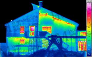
Thermal bridges, insulation deficiencies Thermal bridges are relatively easy to recognize: where the highest temperature is observed in an outdoor image - usually well defined - (and there is no local external heat source or reflection), a thermal bridge (or crack) is present. In indoor images, the coldest spots usually indicate thermal bridges. It is equally easy to determine (with the same external or internal coating) which building element has better or worse insulation properties. Let's see what can be examined:
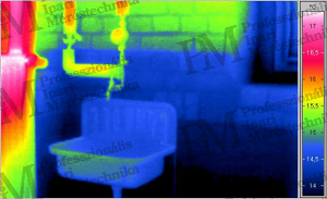
Discovery of hidden building structural and building services elements These measurements must be carried out utilizing various weather- and time-related heat processes. The "trick" may involve measurements after daytime heating (in the absence of subsequent sunlight) (based on heat capacity differences), or measurements based on nocturnal or winter cooling-induced heat flow. In all cases, the heat capacity and thermal conductivity differences between the materials to be inspected (sought) and their surroundings must be exploited according to the desired effect. For example, with proper heat flow, steel and wooden bridging elements in walls become visible using thermographic equipment (due to the high thermal conductivity of steel and the low thermal conductivity and heat capacity of wood between concrete or brick). Based on the same principle, building materials with different properties (alterations, extensions, additions, infills) can also be made visible, or even wall thicknesses can be determined (e.g., for assessing chimney wall construction).
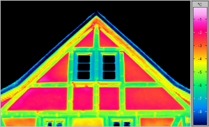
(based on the difference in thermal conductivity between wood and masonry)

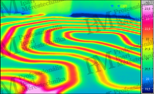
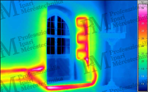
(based on the wall insulation capacity as a function of wall thickness) It is also possible to use thermographic equipment to locate the positions of heating pipes and hot water pipes. These inspections must be carried out during the heating phase to ensure a homogeneous temperature distribution on the surface before conducting thermographic inspections. This method allows for non-destructive verification of the laying (placement) of heating, the density of the laying (e.g., for underfloor heating, wall heating), as well as the length and tightness of pipes, the air-tightness of heating elements and pipes.
Condensation The air in the building always contains a certain amount of moisture in vapor form. The air's moisture retention capacity depends on its temperature. The temperature at which the moisture in the air condenses as dew on a surface is called the dew point. This can naturally occur inside the wall as well because, on the one hand, the wall itself has air- and vapor-permeable properties, and on the other hand, the temperature gradient between the external and internal temperatures can reach the temperature corresponding to the dew point in the wall. Possible causes of condensation damages:
Once we know at what temperature objects (walls) experience condensation due to reaching the dew point under specific air temperature and humidity conditions, based on the following environmental parameters, the internal thermographic image can determine where condensation, mold growth is expected. Moreover, depending on the structure of the wall, not only the risk of condensation (and mold growth) can be identified, but it can also be calculated how long it takes for the building material or insulation to become damp - while maintaining the current use of the room. (Moistening would lead to almost complete loss of insulating properties, so the process must be stopped in any case.)
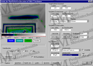
The following parameters are essential for evaluation:
Capillary moisture and leaks During thermographic inspection, the temperature decrease due to heat dissipation caused by evaporating moisture (the required amount of evaporation heat) can be detected. Such inspections naturally require a thermal camera with particularly good thermal resolution. This method can identify the following phenomena: • rising or infiltrating (capillary) moisture from the ground; • leaks due to inadequate sealing of roof connections or gutters; • leaks due to inadequate sealing of sewage pipes.


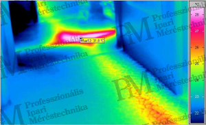
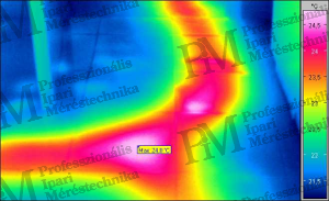
Leak detection and sealing inspections Thermographic leak detection is based on the physical laws of heat conduction. If the temperature of the medium flowing in the pipeline (mostly water) is higher than its surroundings (heating or hot water pipes, underfloor heating, etc.), heat conduction occurs through the surrounding materials to the outer (observable) surface. Therefore, besides the location of the pipeline, the temperature rise caused by the exiting liquid in the surrounding material becomes visible using thermographic tools. It is always valid that leaks can only be detected with thermographic tools if a temperature difference occurs at the leak site, which can be sensed on the observable surface through heat conduction. To detect small leaks, the quantity of the exiting medium must be increased using pressure boosting devices (along with applying maximum temperature). Leaks in cold water pipes can only be found if hot water can be connected to them. Since the exiting medium naturally "flows" within the surrounding material and accumulates in any existing voids, the highest temperature rise occurs where the medium can remain in larger quantities and transfer the corresponding amount of heat to the surrounding material. Therefore, the largest heat effect may not always be visible where the leak is located, but where the exiting medium accumulates. Additionally, detecting leaks is made more difficult if the surface visible with the thermal camera is shiny (reflective, polished, glazed) because the surface's heat radiation-reflective property (low emissivity factor) makes it difficult to detect small heat differences. A completely different problem arises when leaking pipes are concealed behind multiple layers of coverings (e.g., insulation). In such cases, the presence of insulation makes it impossible to recognize the leak location unless the exiting medium flows through the insulation towards the surface to be measured.
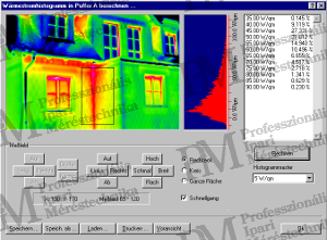
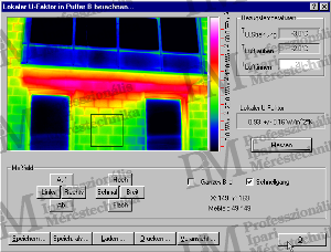
The most important evaluation of quantitative building thermography technology is heat flow, followed by the numerical determination of heat loss based on this. The program performing this - in a very simplified way - assumes that the surface temperature of the external wall is proportional to the amount of heat transported from inside to outside through heat flow. However, it is crucial to adhere to very strict measurement conditions and capture thermal images; otherwise, completely erroneous data will be obtained. Knowing the heat flow, the so-called U-factor, or the numerical value of the heat loss factor, can be determined. Of course, the indoor and outdoor temperatures must be provided for this calculation.
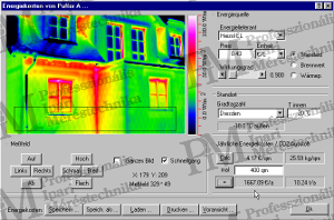
Quantification of heating costs From the heat loss factor, it is a small step to calculate the heating costs. Based on the heat loss factor, it is possible to determine how much energy is needed to heat the building (considering specific climatic conditions, desired indoor temperature, and ventilation habits). If the energy proportional costs of different heating technologies and fuels are known, the expected annual heating costs can be calculated simply by multiplication.
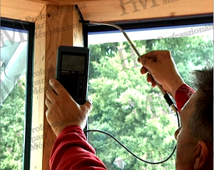
One important element of energy saving is minimizing the air exchange in buildings (but not completely eliminating it, as this would lead to condensation for sure). To achieve this goal, efforts are made to install as tightly closing doors and windows as possible. However, it is often not the unsealed doors and windows that cause the most significant air movement, but rather the incomplete or completely missing vapor barrier foils, poor wall connections, faulty roof sealing, etc., are responsible for drafts. The investigation of where the air flows (in or out) is generally done using the BlowerDoor method: by reducing the internal air pressure by 50 Pa compared to the external pressure with a fan blowing air outwards, air flows in from unsealed areas. The faster the air flows in, the stronger the air exchange, and the more energy is needed to maintain the internal temperature (as the incoming air needs to be constantly heated or cooled). The procedure can be applied year-round: in summer with anemometers and smoke generators, and in winter even combined with thermographic devices. In winter weather, it can be exploited that building elements cooled by cold external air can be well detected with thermographic devices.
![Testing with vacuum produced by a fan [BlowerDoor]](/images/3875/vl4-14-300x241.png)
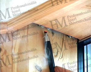
The airflow investigation can reveal the following:
The BlowerDoor technology - supplemented with appropriate instruments - is suitable for further investigations:
Rahne Eric BSc in Electrical Engineering (BME), vibration diagnostics expert, thermography expert (Thermograph Level3) pim-kft.hu, termokamera.hu
The content of the publication is protected by copyright. Any (even partial) use, electronic or printed re-publication is only permitted with the indication of the source and the author's name, and with the author's prior written permission. Violation of copyright (Copyright) will have legal consequences.
Copyright © PIM Professzionális Ipari Méréstechnika Kft.
2026 | Minden jog fenntartva
Impresszum | Adatkezelés