


Eric Rahne, B.Sc. in Electrical Engineering, Level 3 Accredited Thermography Expert (PIM Ltd.)
In the previous part of our series, we discussed the types of building thermography measurements, the necessary measurement conditions, the difficulties and limitations arising from them. In the following part, we will learn about the importance of the geometric resolution requirement based on the capabilities of the thermal camera, the pixel resolution of the thermal image, and the thermal resolution of the thermal camera. All illustrated with real thermal images, drawn from Rahne Eric's 650-page book "Thermography - Theory and Practical Measurement Techniques."
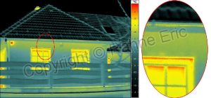
Thermal images taken with a thermal camera under appropriate conditions can reveal various deficiencies related to building structures, insulation, building services, building operation, and moisture/waterproofing. It is important to know that the evaluation is only successful if the appropriate measurement conditions, such as climatic and building operational conditions, were present during the measurement. It is also essential to adhere to the rules of thermographic measurements and, last but not least, that our thermal camera has the appropriate measurement capabilities. Among these, we must also pay attention to the geometric resolution: for example, measuring a panel building from the 10th floor from the ground (let's say from a distance of 60 m) using the Pythagorean theorem √302 + 602 = 67 m results in a real measurement distance. For a thermal camera with a 2 mrad resolution, this allows measuring surfaces of only 402 mm (thus 40 cm). Such a thermal image contains at most the information about how many windows there are on the 10th floor! The following thermal images illustrate the situation with an example of a walking grid holder.
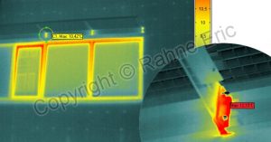
Building capture with a standard lens - smallest measurable object: 15 m x 0.8 mrad x 3 = 36 mm, maximum temperature 10.4°C; circle-marked telephoto capture: smallest measurable object: 5 m x 0.4 mrad x 3 = 4 mm, maximum temperature 12.2°C. As the above thermal images prove, building thermography - although dealing with large measurement objects - cannot avoid the issue of geometric resolution. The sought-after problems simply become "invisible" if the requirement for geometric resolution is ignored. This situation can be remedied by using interchangeable lenses available for professional thermal cameras. In addition to geometric resolution (i.e., the size of the object surface "pixel" corresponding to a unique sensor), the image quality achievable with a thermal camera, or more precisely, the detail of the measurement, is determined by the number of pixels of the thermal camera. The reason for this is that for graphic (visual) recognition, a certain minimum number of pixels must fall on certain parts of the object to be measured - just as we are used to in digital photography. It is easy to understand that with more pixels, we can represent the object surface with greater detail or the same level of detail over a larger object surface in a single thermal image. If there are few pixels, many images need to be taken, and for evaluating continuous objects and preparing reports, it often becomes necessary to montage the images (which is a very time-consuming task). This issue is not insignificant for thermal cameras. While in digital cameras we talk about resolutions of 10, 12, or even more than 20 megapixels (20 million pixels), in average matrix thermal cameras, the number of pixels is typically 320x240 (thus 76,800) or 384x288, and in professional thermal cameras, it is 640x480 (thus 307,200) or even 1024x768 (thus 786,432) pixels. There are also cameras with lower capabilities - a common type has 160x120 (thus only 19,200) pixels or even just 80x80 or 96x96 pixels, which consequently can only display smaller surfaces with acceptable detail, severely limiting their area of application or even making the thermal camera unusable for certain tasks. It is interesting that the price per pixel of professional thermal cameras with a 640x480 or 1024x768 pixel sensor matrix is the most favorable (even by an order of magnitude) compared to low-resolution - so-called Low-Cost - thermal cameras.
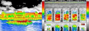
The following figures vividly demonstrate the effect of the number of pixels on the efficiency of the workflow. The image on the right (640x480 pixels) was taken with a single on-site button press and - since it contains all the information of the inspected building side - can also be inserted into the report with just a single click. In contrast, the thermal image on the left (160x120 pixels) can only capture a smaller part of the building side with the same geometric resolution. To achieve the completeness and quality of the image on the right, 16 times as many pixels - hence as many thermal images - would be needed. However, since the montage of thermal images requires even the overlap of individual thermal images, we are forced to take many more - even 20 ... 25 thermal images on-site. Naturally, the acquisition time for a 640x480 pixel thermal image is several times longer.
The real inconvenience, however, awaits us during report preparation, as we are faced with the time-consuming task of montage for 20-25 thermal images, which depending on our skill can take between 30 minutes and several hours.
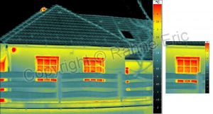
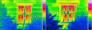
Therefore, it is worth considering whether to opt for a thermal camera with a smaller number of pixels for a smaller investment (and pay for our savings with multiple additional work), or to acquire an economical tool necessary for efficient work by choosing a thermal camera with a higher number of pixels.Now, one might argue that, of course, we can capture the entire side of the building with a 160x120 pixel thermal camera. However, the price for this will be the inadequate geometric resolution, as demonstrated by the following two images. The reference thermal image is again the 640x480 pixel resolution image shown on the previous page (with slightly different thermal scaling), while the cost-saving test image was taken with 160x120 pixels from exactly the same building. Both thermal images were depicted in the same size, and we zoomed in on the same "object" surface to highlight the difference (and thus the usability of the images).
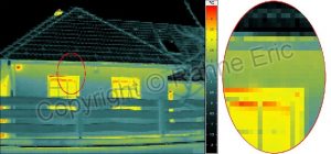
Without delving into any lengthy explanations, even an inexperienced observer will immediately see that the above 640x480 pixel thermogram allows for evaluating the quality of window frame installation (wall connection) and window sealing. However, the lower thermal image (with only 160x120 pixel resolution) does not offer this possibility, so in this case presented here, the purpose of thermal evaluation of buildings cannot be achieved. Especially when the temperatures to be measured are close to the lower limit of the thermal camera's current measurement range (which is typical in building thermography), the image quality is predominantly determined by the thermal resolution capability of the thermal camera. The parameter that characterizes this - the "NETD" (Noise Equivalent Temperature Difference) - specifies the effective value of the camera's own noise expressed in the temperature difference of the object that results in the same electrical signal. This parameter, which qualifies the thermal camera, is determined at 30°C in accordance with the requirements of the DIN EN 16714-2:2016-11 standard, assuming an ideal radiator as a reference object. It is important to know that this NETD value (usually given as a single number) unfortunately is not the same at all temperatures, not true for all measurement ranges of the thermal camera, and not for each (replacement) lens application. Nevertheless, this figure is the most common and practically the only information we have regarding the expected noise level of our thermal image. It should be noted that by reducing the object temperature, the noise level almost exponentially increases (thus deteriorating the thermal resolution). This is entirely logical, as with decreasing temperature, the amount of radiation decreases exponentially, so the signal-to-noise ratio deteriorates just as rapidly. It follows that the thermal resolution given at 30°C is not valid for lower object temperatures; toward 0°C, the NETD value can even double.
The thermal resolution of the thermal camera naturally affects the recognizability of details in the thermal image through the smallest temperature differences that can be detected. Unfortunately, this situation is further worsened by the limit of our eye's color and grayscale difference perception, as well as the necessity of displaying the appropriate quantity of "identical" pixels to recognize it as a coherent "surface." Numerical exampleFrom a thermal camera with a +/-120 mK (+/-0.12°C) temperature resolution valid at 30°C, in practice, at 0°C, there will already be a +/-0.25°C noise "easily." Since this value is per pixel, the total temperature resolution of the thermal image is only 0.5°C (as the pixels can deviate from their placement and each other independently up to the maximum value). For the visually coherent surface on the thermal image to be recognized, the surface temperature must differ by at least twice the above value from the surrounding thermal image pixels - thus, the minimal temperature difference representing the limit of recognizability in this example is nearly 1°C (for measured object temperatures around 0°C)! Rahne Eric (PIM Ltd.) pim-kft.hu, termokamera.hu
The content of the publication is protected by copyright. Any (even partial) use, electronic or printed re-publication is only permitted with the indication of the source and the author's name, and with the author's prior written permission. Violation of copyright (Copyright) entails legal consequences.
Copyright © PIM Professzionális Ipari Méréstechnika Kft.
2026 | Minden jog fenntartva
Impresszum | Adatkezelés