


Eric Rahne, B.Sc. in Electrical Engineering, forensic expert (PIM Ltd.)
One of the most important elements of buildings in terms of energy is their external "cladding" - the walls, windows, and roof. It is essential that these elements have the best possible thermal insulation properties (lowest thermal conductivity and lowest emissivity). The execution of joints and connections, structural thermal bridges caused by building elements, as well as "damage" from building services or electrical installations in external walls can also be examined. Nowadays, when architecture and building services are getting closer (passive house!), this is an important topic.
In order to not only take beautiful colorful images of the building to be inspected with the thermal camera, but also to produce thermal images that can be evaluated by architects, energy experts, structural engineers, and operators - allowing for correct conclusions - the following minimum requirements must be met: • External images should be taken in the early morning or late evening hours (during periods without direct sunlight), in dry weather, with calm winds (up to a gentle breeze, <2 m/s wind speed). • The temperature difference between indoor and outdoor should be at least 15-20 K. • The indoor area should be uniformly heated (internal doors open), with external openings tightly closed. • The automatic night mode of the heating system (if available) should be turned off (thus the full heating system should be operational). From the above, it follows that building thermography can only be carried out during the heating season, in appropriately cold (below 5°C) weather.
When producing high-quality, evaluable thermal images, there are also significant expectations placed on the thermal camera itself. Without meeting these requirements, we would obtain unrecognizable thermal images incapable of detecting faults. The thermal camera must minimally meet the first six points of the following list: • high thermal resolution (–0.08 K or better), • as many pixels as possible (minimum 320x240 pixels), • low noise level, good signal-to-noise ratio (cameras calibrated from -40°C meet this requirement), • temperature range from -20°C to +100°C (preferably from -40°C), • operating temperature range from -10°C (preferably from -20°C), • high geometric resolution (1.5 mrad or better), • telephoto lens for certain measurements, • easy handling (e.g., automatic focus), • large storage capacity (preferably a minimum of 200 thermal images), • versatile evaluation and documentation PC software. Unfortunately, the emissivity factor depends on the viewing angle as well, so we must consider that the more the viewing angle deviates from the right angle, the more increasing reflection is observed. This effect can be observed mainly in measurements of curved surfaces, but for example, when measuring the upper floors of tall buildings, we also face this issue: seemingly, the upper floors appear cooler (although in reality, they are getting warmer). The explanation is that the sky (without clouds at -273°C) is increasingly reflected on the external surface of the building, despite the emissivity factor of approximately 95% for surfaces made of silicate-based building materials. Beyond geometric resolution, the quality of the thermal image that can be achieved with a thermal camera - or more precisely, the detail of the measurement - is determined by the number of pixels of the thermal camera. While in digital cameras we talk about resolutions of 5, 6, 7, or even more than 10 megapixels (10 million pixels), in matrix thermal cameras, the number of pixels is typically 320x240 (thus 76,800 pixels). There are also cameras with lower capabilities - the 160x120 resolution type is common (with only 19,200 pixels) - which are therefore only capable of displaying smaller areas with acceptable detail. The following thermal images vividly demonstrate the effect of the number of pixels on the detail of the thermal image.
If we have adhered to the measurement conditions detailed in the framework section, we only need to learn how to evaluate and analyze the measurement results obtained in this way (graphically represented, i.e., the thermal images). Therefore, we separately discuss the appearance and detectability of the most common structural and building services defects. Thermal bridges, insulation deficiencies Thermal bridges can be relatively easily identified: where on an outdoor image - usually well delineated - the highest temperature is observed (and there is no local external heat source or reflection), a thermal bridge (or crack) is present. In indoor images, the coldest spots usually indicate thermal bridges. It is equally easy to determine (with the same external and internal coating) which building element has better or worse thermal insulation properties. Let's see what can be examined: • assessment of renovation needs in old buildings (e.g., condition of windows, insulation of walls, execution of joints and connections); • verification of external insulation execution in new and renovated buildings, as well as at the connections of subsequent building parts, balconies, etc.; • occurrence of structural thermal bridges due to bridging elements (e.g., steel beams); • condition of joints (particularly interesting in prefabricated panel buildings); • "gaps" in external walls from building services installations. Discovery of hidden building construction and building services elements These measurements must be carried out by exploiting various thermal processes related to weather conditions and time of day. The "trick" may involve measurements taken after daytime heating (in a period without subsequent sunlight) based on differences in heat capacity, or measurements based on heat flow due to nighttime or winter cooling. In all cases, the differences in heat capacity and heat conduction between the materials being inspected (sought) and their surroundings must be exploited according to the desired effect. For example, with proper heat flow, steel and wooden bridging elements in a wall become visible using thermographic tools. (Due to its high thermal conductivity, steel becomes visible, while wood becomes visible between concrete or brick due to its low thermal conductivity and heat capacity.) Based on the same principle, building materials with different properties (reconstructions, extensions, additions, bricking up) can also be made visible, or even wall thicknesses can be determined (e.g., for assessing chimney walling).
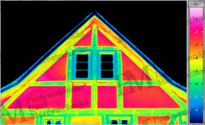
(based on the difference in thermal conductivity of wood and masonry)
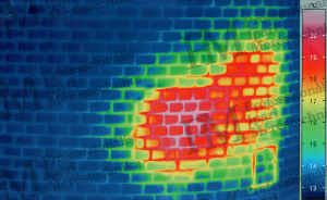
(based on the dependence of masonry insulation capacity on wall thickness) It is also possible to use thermographic tools to locate the positions of heating pipes and hot water pipes. These inspections must be carried out during the heating phase using thermographic inspection before the surface reaches a homogeneous temperature distribution. This method allows for the non-destructive verification of the laying (placement) of heating, the density of the laying (for example, in underfloor heating, wall heating), as well as the length and tightness of the pipes, the air tightness of heating elements and pipes.

Condensation The air in the building always contains a certain amount of moisture in vapor form. The air's moisture retention capacity depends on its temperature. The temperature at which the moisture in the air condenses as liquid on surfaces at that temperature is called the dew point. This can naturally occur inside the walls as well, as the wall itself has air and moisture permeability, and the temperature gradient between the external and internal temperatures can reach the temperature associated with the dew point. Possible causes of condensation damage: • inadequate insulation (primarily noticeable at room corners or lintels, concrete sills); • poor building operation (inadequate heating or ventilation). Once we know at what temperature dew point is reached on certain surfaces (walls) under specific air temperature and humidity conditions, considering the environmental parameters listed below, it is possible to determine where condensation and mold growth are expected based on internal thermal imaging. Furthermore, depending on the construction of the wall structure, it is not only possible to detect the risk of condensation (and mold growth), but also to calculate how long it will take for the building material and insulation to become damp while maintaining the current use of the room. (Excessive dampness would lead to almost complete loss of insulating properties, therefore the process must be stopped.) Essential parameters for evaluation: • internal and external air temperature and relative humidity at the time of measurement • ventilation and room use at the time of measurement • typical use of the examined room (living room, office, bedroom, warehouse, etc.) • climatic data (e.g., lowest winter temperature, highest relative humidity) • volume of the examined room, ventilation speed, moisture load (e.g., from human respiration) Capillary moisture, as well as leaks During thermographic inspection, the temperature decrease caused by the heat dissipation due to evaporating moisture (the required amount of heat for evaporation) can be detected. This type of inspection requires a thermal camera with particularly good thermal resolution. The following phenomena can be identified using this method: • rising or infiltrating (capillary) moisture from the ground; • leaks due to poorly sealed roof connections or gutters; • leaks due to poorly sealed sewage pipes.
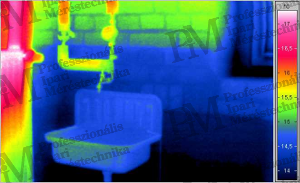
(infiltration from the ground) [source: Infratec] Leak detection, finding leaks Thermographic leak detection is based on the physical laws of heat conduction. If the temperature of the medium flowing in the pipe system (mostly water) is higher than its surroundings (heating or hot water pipes, underfloor heating...), heat conduction occurs through the surrounding materials to the outer (observable) surface. Thus, in addition to the location of the pipe, the temperature increase caused by the exiting liquid in the surrounding material can be observed using thermographic tools. It is always valid that leaks can only be detected with thermographic tools if a temperature difference is created at the leak site, which can be sensed on the observable surface through heat conduction. To detect minor leaks, it is necessary to increase the amount of the exiting medium using pressure boosting devices (while applying maximum temperature). Leaks in cold water pipes can only be found if hot water can be connected to them. Since the exiting medium naturally "flows away" within the surrounding material and collects in any existing voids, the greatest temperature rise occurs where the medium can remain in larger quantities and transfer the appropriate amount of heat to the surrounding material according to its heat capacity. Therefore, the largest heat effect is not always visible where the leak is located, but where the exiting medium accumulates. Additionally, finding leaks is further complicated if the surface visible with the thermal camera is shiny (reflective, polished, glazed), as the surface's heat radiation-reflective property (low emissivity factor) makes it difficult to detect small temperature differences. A completely different type of problem arises if the leaking pipes are concealed behind multiple layers of coverings (e.g., behind insulation). In such cases, the presence of insulation makes it impossible to identify the leak location unless the exiting medium flows through the insulation towards the surface being measured. Quantitative methods The most important evaluation in quantitative building thermography technology is the heat flow, followed by the numerical determination of heat loss based on this. The program performing this calculation - simplifying greatly - assumes that the surface temperature of the external wall is proportional to the amount of heat transported from inside to outside through heat flow. However, it is crucial to adhere to very strict measurement conditions and capture thermal images; otherwise, completely erroneous data will be obtained. Knowing the heat flow, the so-called U-factor, or the numerical value of the heat loss factor, can be determined accordingly.Of course, the indoor and outdoor temperatures must be provided for this. Quantification of Heating Costs Calculating heating costs is not a big step from the heat loss factor. Based on the heat loss factor, it can be determined how much energy is needed to heat the building (taking into account specific climatic conditions, the desired indoor temperature, and ventilation habits). If the energy proportional costs of different heating technologies and fuels are known, the expected annual heating costs can be determined by simple multiplication.
One important element of energy savings is minimizing the air exchange rate in the property (but not completely eliminating it, as this would lead to condensation for sure). To achieve this goal, efforts are made to install tightly sealed doors and windows. However, often the biggest air movement is not caused by unsealed doors and windows, but by missing or completely absent vapor barriers, poor wall connections, faulty roof seals, etc. responsible for drafts. The examination of where the air flows (in or out) is generally done with the BlowerDoor method: a fan blowing air outwards reduces the internal air pressure by 50 Pa compared to the outside, causing air to flow in from unsealed areas. The faster the air flows in, the stronger the air exchange, and the more energy is needed to maintain the internal temperature (as the incoming air needs to be constantly heated or cooled). The procedure can be applied year-round: in summer with anemometer airspeed meters and fog generators, and in winter even combined with thermographic devices. In winter weather, it can be exploited that building elements cooled by cold outside air can be well detected with thermographic devices. The airflow examination can reveal the following: • faulty window-frame-wall connections, or poorly sealed or deformed doors and windows; • poorly sealed blinds, or their mounting covers; • poorly insulated attic hatches in ventilated roof spaces; • mounting cutouts in plasterboard walls (electrical installations, etc.); • errors in transitions between attic and base walls, as well as lightweight and traditional building components; • incomplete attic vapor and air barrier foils. The BlowerDoor technology - supplemented with appropriate instruments - is also suitable for further examinations: • determination of air exchange rates per level and zone (with multi-channel pressure measurement); • examination of the operation and efficiency of ventilation systems (with pressure difference measurement); • checking the operation of exhaust systems and chimneys (with pressure difference and airspeed measurement); • detection of flue gas backflow (with carbon dioxide and carbon monoxide sensors). Rahne Eric (PIM Ltd.) pim-kft.hu, termokamera.hu
The content of this publication is protected by copyright, and its (even partial) use, electronic or printed re-publication is only permitted with the indication of the source and author's name, and with the author's prior written permission. Violation of copyright (Copyright) entails legal consequences.
Copyright © PIM Professzionális Ipari Méréstechnika Kft.
2026 | Minden jog fenntartva
Impresszum | Adatkezelés