


Eric Rahne, B.Sc. in Electrical Engineering, forensic expert (PIM Ltd.)
One of the most important elements of buildings in terms of energy is their external "envelope" - the walls, windows, and roof. It is essential for these elements to have the best possible thermal insulation properties (low thermal conductivity and low emissivity). Thermal bridges can be relatively easily identified: where the highest temperature is observed in an outdoor image, there is usually a thermal bridge (or crack). In indoor images, the coldest spots usually indicate thermal bridges. Similarly, it can be determined which building element has better or worse insulation properties. The execution of joints and connections, structural thermal bridges caused by building elements, as well as "damage" from building services or electrical installations in external walls can also be examined. Nowadays, when architecture and building services are getting closer (passive house!), this is an important topic.
A basic requirement for all measurements is that the temperature difference between indoor and outdoor is at least 15 K, the wall is not wet from rain, there is no wind, and the measurement is done during a sunny period without direct sunlight. The accuracy of thermographic (thermal imaging) temperature sensing primarily depends on the emissivity of the measured surface. The lower the emissivity of a surface, the more important the correction calculation, which, in addition to this factor, is based on the exact knowledge of the ambient temperature (for thermal radiation-transparent bodies) and the background temperature. The emissivity of materials depends on the material itself, surface roughness, wavelength, and viewing angle. This relationship implies that in some cases, the temperature of an object cannot be measured: • in the case of reflective surfaces - e.g. polished surfaces, oxidation-free metal surfaces, • for materials transparent to infrared radiation - e.g. certain crystalline materials, various gases. A similar situation arises when examining glass surfaces: it is characteristic that glass transmits radiation shorter than 3.5 µm (such as sunlight and shortwave thermal radiation), but does not transmit radiation longer than 3.5 µm (e.g. radiation from lower temperature bodies). In the long-wave range (long-wave atmospheric window: 8 ... 14 µm), glass does not have transmissive properties, yet it has an emissivity factor of only 60% due to its reflective properties. Moreover, as a "polished" surface, the degree of reflection increases further if the image is not taken at a right angle. Naturally, dirt (dust) on the glass slightly increases the emissivity, but this is an uncertain and practically negligible factor. In summary, long-wave thermal cameras (such as the currently predominantly used so-called real-time matrix - bolometer - cameras, which are the most common for building thermography) detect glass as a mirror, so measuring the temperature of glass surfaces with such devices is not feasible. (Note: With short-wave cameras - depending on the additional filter - we can either see through the glass or measure the surface temperature of the glass, if the temperature is above 100°C. In the case of very high temperatures, it is possible to measure the temperature of glass surfaces with long-wave cameras using very special filters, but this is very rarely done.) During thermographic inspections, temperature decrease due to evaporative heat loss caused by moisture can also be detected. This requires a particularly high thermal resolution camera. This method can be used to identify leaks due to faulty roof connections, gutters or sewage pipes, as well as moisture seeping up from the ground or infiltrating, and moisture accumulated in building materials due to condensation.
Building thermographic images must meet certain measurement conditions and thermal camera quality parameters in order for the measurement results to be evaluated. Very often (also in the mentioned audit report), there are issues with the temperature resolution, geometric resolution, and pixel resolution of the thermal image. (Note: the cause of this is usually the selection of inadequate - too low-power - thermal cameras and the incomplete professional qualifications of the installer.) Temperature resolution Especially when the range to be measured falls between room temperature and the lower limit of the measurement range, the temperature resolution predominantly determines the image quality. The "NETD" (noise equivalent temperature difference) represents the effective value of the camera's own noise, expressed in the temperature difference of the object that results in the same electrical signal magnitude (usually measured at 30°C). (In other words: "NETD" is the value of the temperature change that results in the same electrical signal change as the camera's own noise.) This value increases significantly when the object's temperature is reduced, especially for short-wave devices. Since temperature differences of less than 0.5°C need to be recognized in building thermographic measurements and the "noise level" required for this should be less than half of this, i.e., 0.25°C, or more precisely +/-0.12°C. Since thermal camera manufacturers define the NETD value at 30°C and this value deteriorates significantly at lower temperatures, for typical outdoor temperatures during building thermographic measurements (-15°C ... +5°C), a thermal camera with at least +/-0.08°C NETD value (or in other words: thermal resolution) must be selected. With lower quality thermal cameras, the aforementioned building defects cannot be identified! Geometric resolution In addition to temperature resolution, geometric resolution also significantly affects the achievable image quality and the authenticity of the image's temperature data. The IFOV parameter influencing this (smallest elemental field of view, typically given in mrad) provides the viewing angle that has been imaged with a unique sensor (pixel). To reproduce details well, it is important for this value to be as small as possible.
For example, a 1.5 mrad IFOV indicates that each individual measurement point assigned to every pixel (projected measurement spot) has a diameter of 1.5 mm at a distance of 1m.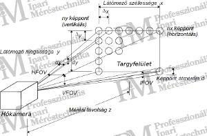
Since we do not know the position of the "projected" image point on the object to be measured and the sensor matrix itself (due to manufacturing gaps), the above point size should be multiplied by 3 to determine the smallest measurable object size. Failure to do so may result in the measurement spot containing radiation not only from the object's surface but also from its background. Due to averaging within the measurement spot, the measurement result may be either lower or higher than the actual temperature of the object due to the background temperature. The greater the temperature difference between the object and the background, the greater the measurement error will be! Of course, this rule applies not only to small objects (e.g., thin wires, filaments, etc.) but also to large objects (e.g., large cross-sectional cables, doors, etc.) during measurements. Obviously, different dimensions are involved: for small objects, we are talking about measurement surfaces on the order of millimeters, which can be measured from distances of up to several tens of centimeters based on the geometric resolution of the applied thermal camera and optics; for large objects, we are talking about measurement surfaces in the order of centimeters that can be sensed from distances of several meters (up to 10 meters). In all cases, the use of devices that allow compliance with the above rule is necessary! Concrete example:If we want to measure a ten-story panel building, then to measure the upper floors (at about 30 meters in height), we need to work from a distance of about 60-70 m to minimize geometric distortion of the image (to avoid perspective effects). According to Pythagoras, the distance between the thermal camera and the object is then 67 - 76 m, so with a thermal camera with a resolution of 1.3 - 1.4 mrad (the geometric resolution achievable with standard lenses in most professional cameras), the elementary measurement point has a diameter of 87 - 106 mm, so the smallest measurable object must be larger than 261 or 318 mm! (As a reminder: a window frame is rarely wider than 70 mm). Therefore, the use of a telephoto lens is necessary, providing a geometric resolution of 0.2 - 0.5 mrad depending on the camera type.Number of pixels In addition to geometric resolution, the image quality achievable with a thermal camera - or more precisely, the detail of the measurement - is determined by the number of pixels in the thermal camera image. This is because, for graphic recognition, a certain minimum number of pixels must fall on different parts of the object being measured - just as we are used to in digital photography. It is easy to understand that with more pixels, we can represent the object surface with greater detail, or the same level of detail over a larger object surface in a single thermal image. If the number of pixels is low, many images need to be taken, and for evaluating continuous objects and preparing reports, it often becomes necessary to montage the images (which is a very time-consuming task). This issue is not insignificant for thermal cameras. While in digital cameras we talk about resolutions of 5, 6, 7 or even more than 10 megapixels (10 million pixels), in matrix thermal cameras, the number of pixels is typically 320x240 (thus 76,800 pixels). There are also cameras with lower capabilities (a common type is 160x120, with only 19,200 pixels), which can only display surfaces of acceptable detail, limiting their area of application (but they are very affordable). Thanks to the development of thermal camera sensors, thermal cameras with an increasing number of pixels are being produced. Thermal cameras with sensor matrices containing 384x288 elemental sensors are available at an acceptable price, and even devices with sensor matrices of 640x480 pixels are available (with 50 or 60 Hz frame rates). In building thermography, acceptable image quality (or more precisely: detail) is achieved by using a 320x240 pixel thermal camera to take "overview" thermal images of wall details up to 2 floors, as one pixel is captured every 25 millimeters in such cases (remember: with averaging!). Depending on the camera lens - with a standard lens - this typically means a measurement distance of 15 m (with a geometric resolution of 1.5 mrad, the pixel size is then 22.5 mm, so the smallest - accurately measurable - object size is 67.5 mm!). For capturing details, additional shots must be taken from closer or with a telephoto lens.
The primary purpose of building thermography is the objective and comprehensive assessment of building insulation. However, never forget that thermographic measurement serves to capture the momentary surface temperatures, influenced by various measurement conditions. Regarding buildings, the following thermographic procedures are fundamentally distinguished: Quantitative Thermographic Inspections The goal of quantitative building thermography is to evaluate the complete surface temperature distribution of a building and determine the thermal transmittance coefficient (e.g., for calculating heat loss or heating energy requirements). Since the coefficient can only be calculated based on very accurate (absolutely precise) temperature data, very strict conditions must be met for data collection with a thermal camera. The procedure is characterized by * high evaluation requirements, * strong limitations in terms of season, time of day, and weather, * can only be performed after several rain-free days and in calm weather, * can only be applied under steady-state heat flow conditions (early morning or late evening), * additional indoor measurements are necessary to establish reference points. Qualitative Thermographic Inspections The purpose of qualitative thermal imaging building inspections is to search for and document the building's thermal bridges and insulation "defects" (qualitative differences). Most problems can be detected based on heat differences that can be displayed with a thermal camera with sufficiently high temperature resolution; in this case, absolute (numerically exact) temperature data play a minor role.The characteristics of the procedure are: * fewer restrictions regarding measurement conditions, * weaker limitations in terms of season, time of day, and weather, * can only be carried out on rain-free days and in calm weather, * can only be applied under steady-state heat flow conditions (early morning or late evening). Both quantitative and qualitative thermographic building inspections should include both indoor and outdoor inspections. In fact, for quantitative inspections, indoor measurements are practically mandatory, as this is the only way to calculate the heat flow properties of individual surfaces. Our table provides an overview of the measurement conditions to consider during indoor and outdoor measurements, as well as the differences (difficulties) between the execution of the measurements. Differences between indoor and outdoor thermographic inspections
| Outdoor thermography | Indoor thermography |
| Generally, the entire wall surface is well visible (good visibility). | Often only certain parts of the walls can be measured, and essential surfaces may be inaccessible. |
| Adjustable recording positions. | Visibility is often highly restricted due to existing furniture or building services elements. |
| Low time requirement, does not disturb the building user. | Requires a long preparation time, disturbs the building user. |
| Strongly weather-dependent, can only be done in sunny weather. | Weather has no direct impact (although the effect is significantly weakened). Under certain conditions, it can also be done during the day. |
| Problematic for roof structures and ventilated building claddings. | More assessable for roof structures and ventilated building claddings. |
| Difficulty in covering external surfaces with trees, balconies, building decorations. | Deficiencies in air insulation (drafts) are more noticeable in windy conditions. |
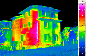
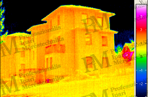
Table 1: Differences between indoor and outdoor thermographic inspections Following the importance of adhering to the above rules, let's present examples of thermal images: Left image: building survey during the day (unfinished construction) Right image: building survey three hours after sunset - the sun's radiation is reflected on the building walls - the heating effect of the daytime sun is already apparent - the walls seem warm, although there is no heating !!! barely noticeable, so now we can measure
Left image: thermographic survey conducted in strong winds Right image: the same survey in calm weather - the wind takes away the heat from the right-side wall, making it cooler - it appears that the right-side wall insulation - seems better than that of the wall in the middle of the thermal image (with the same weak thermal bridges)
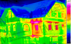
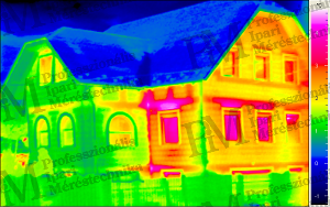
Note for both thermal images: the left side of the building is not heated (staircase) Rahne Eric (PIM Ltd.) pim-kft.hu, termokamera.hu
The content of the publication is protected by copyright, and its (even partial) use, electronic or printed republication, is only permitted with the indication of the source and the author's name, and with the author's prior written permission. Infringement of copyright (Copyright) will result in legal consequences.
Copyright © PIM Professzionális Ipari Méréstechnika Kft.
2026 | Minden jog fenntartva
Impresszum | Adatkezelés