


"Accurate temperature measurement or spectacular visualization?"
According to some manufacturers, their methods can achieve more precise measurements, create sharper and more analyzable thermal images while reducing the loss of temperature information. However, a professional review of the advertised methods often reveals that these statements are misleading.
According to FLIR's own information, the MSX method involves the insertion of the photo's contrast lines into the thermal image. The result - according to the manufacturer - provides extremely high-contrast and sharp thermal images. However, based on the knowledge shared in our series of articles so far, it is already known that this claim does not hold up. Only the visual appearance improves, there is no improvement or clarification in the measurement data content, and the sharpness does not increase. Moreover, any potential warnings about poor focusing or insufficient geometric resolution (or too small pixel resolution) are actually hidden. Therefore, this method does not support us in determining the object's temperature more accurately or correctly.
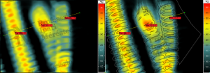
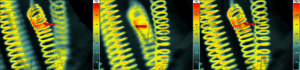
The mentioned method is similar to applying an edge-finding algorithm on a photo and projecting its result onto the thermal image. This seemingly brings out the edges of the measured objects, making the thermal image visually sharper. This way, even a thermal image that is completely unsuitable for evaluation can be made visually appealing, but the measurement data remains uncorrected. Therefore, the temperatures remain just as accurate (or inaccurate) as without the MSX method. Manual and autofocus, depth of field enhancement It is not easy to determine during thermal imaging if the focus is truly accurate. This is difficult due to the radiophysical (optical) conditions of thermography, as an object emits radiation even at its edge, so there is no "sharp" edge (contour) as we are used to in the visually reflected radiation-based world of everyday life. To aid in this, many thermal cameras incorporate an autofocus function, which can only be achieved if the optics are motorized. However, it is important to note that thermal cameras have technical limits to their autofocus - similar to the procedures used in digital photography for this purpose. In the case of thermal cameras, the procedure involves the software searching for the steepest temperature gradients within the designated focus area, i.e., those pixel groups where the temperature changes most significantly over the smallest pixel distance. This is likely to be an edge of a perceived object. The next step involves adjusting the focus optically until the previously found gradient reaches its maximum steepness. This is presumably the best focus setting for this object edge. However, not all problems are solved with this, as thermal cameras have a very shallow depth of field. As a result, objects or details that are slightly closer or further away will appear blurred. Therefore, it is necessary to decide which part of the object is most important and focus on that specifically. The images in Figure 3 illustrate this dilemma with our series' measurement object, a heating fan. In this case, the heating elements of interest are located 15 mm apart from each other. Despite our best efforts at a 40 cm measurement distance, we can only focus sharply on either the closer or the further element. What if we want to see both sharply? For example, the Jenoptik EverSharp method enables the simultaneous sharp display of both the closer and further heating elements. The thermal camera takes multiple images around the autofocus setting (capturing further and closer "layers") and merges them to highlight the sharp details. However, this thermal image is not a graphically enhanced display but a data file sharply focused in every detail and depth.
Final Conclusion In summary, neither interpolation, composite visualization obtained by projecting a photo onto a thermal image (fusion), nor MSX technology helps with the pixel resolution or geometric resolution of thermal images, does not improve focusing inaccuracies, and does not increase depth of field. Instead, they result in a deceivingly "higher quality" visual appearance that hides inaccurate or even completely uninterpretable temperature data, as well as the visual phenomena indicating them. All three methods are exclusively applicable for visually enhancing thermal images based solely on accurate temperature data for documentation purposes. Enhancing the measurement capabilities of a thermal camera or correcting inaccurate measurement data is impossible with these methods. The EverSharp method is suitable for improving the depth of field issue, which Fluke has been advertising as a "unique" novelty under the name MultiSharp for some time for certain mid-range thermal cameras.Presumably, however, this method is identical to the EverSharp procedure implemented in Jenoptik VarioCAM HD cameras on the market since 2012. Therefore, it is presumably not as unique as the advertisement suggests. The Jenoptik GmbH EverSharp method is suitable for improving depth of field issues, which is implemented in the VarioCAM HD cameras on the market since 2012. Presumably, this method is identical to the Fluke company's MultiSharp, which has been advertised for some time as a "unique" innovation. (Therefore, it is presumably not as unique as the advertisement suggests.) Rahne Eric (PIM Ltd.) pim-kft.hu, termokamera.hu
The content of the publication is protected by copyright, and its (even partial) use, electronic or printed further publication is only permitted with the indication of the source and the author's name, as well as with the author's prior written permission. Violation of copyright (Copyright) will have legal consequences.
Copyright © PIM Professzionális Ipari Méréstechnika Kft.
2026 | Minden jog fenntartva
Impresszum | Adatkezelés