


Eric Rahne, B.Sc. in Electrical Engineering, Level 3 Accredited Thermography Expert (PIM Ltd.)
In our series of articles, we aim to provide insights into the incredible versatility and theoretical as well as practical limitations of thermography, drawing from Eric Rahne's 650-page book "Thermography - Theory and Practical Measurement Technology." In this article, we focus on the fact that in buildings, temperature differences caused not only by thermal bridges and unwanted airflows present challenges in themselves, but also mold growth or structural dampness resulting from water vapor transport and condensation related to these issues.
It is a fact that in a residential building, moisture, water vapor is constantly generated during habitual use. This includes our breathing, which can result in 20 to 70 grams of water vapor per person per hour at rest, and up to 200 to 300 grams under physical exertion. Cooking, washing, and bathing/showering can result in 800 to 2000 grams of water vapor per hour. Let's not forget about pets and indoor plants, as they can produce 5 to 30 grams of water vapor per individual per hour, depending on their size. This water vapor, moisture enters the indoor air of the building, and its humidity increases continuously in the absence of ventilation or other moisture-reducing processes.
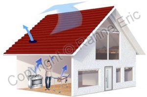
However, air can only absorb and retain water vapor, moisture to a limited extent. This ability depends on the air temperature. Since both air and water vapor have their own mass, atmospheric pressure results from the sum of the air pressure and the so-called vapor pressure. Vapor pressure is highest when the air becomes saturated with water vapor, meaning it cannot absorb more water vapor at the given temperature. The dew point is the temperature at which, at constant pressure, the air becomes saturated when cooled. In practice, this is the temperature at which moisture in the air condenses and forms condensation on surfaces of the same temperature. This condensation can also occur inside a wall or insulating material, as most building materials have some degree of air or vapor permeability and the temperature gradient between the exterior and interior can reach the dew point. Most condensation and moisture-related problems and building damages can be explained by this relationship.
The greater the difference in vapor pressures and the lower the material's vapor diffusion resistance, the more intense the water vapor transport towards the lower vapor pressure space. The material's δ vapor diffusion factor or the layer's RP vapor diffusion resistance, similar to thermal resistance, can be treated as material-specific data. There is also a µ vapor diffusion resistance ratio, which indicates the material's relative vapor diffusion capacity compared to air's vapor diffusion resistance. In this case, it is a dimensionless ratio (Table 1).
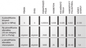
Generally, materials with smaller pore structures, typically denser materials, have the highest vapor diffusion resistance. Among similar materials, closed-cell porous materials have higher resistance compared to open-cell porous ones. When discussing material properties, let's also consider another phenomenon known as capillarity or capillary action, which is architecturally important. Most building materials have significant capillarity, which practically characterizes the material's water absorption capacity. This property is influenced by the material's porosity, water's cohesive forces or surface tension, and the adhesive forces attracting water molecules to each other. Assuming appropriate small pores, these forces can be greater than gravitational force, allowing water to "climb" upwards in materials due to capillary action. It can be generally stated that capillary action increases with material porosity and fineness of pores. Greater density and porelessness of the material reduce capillarity. For example, in concrete with pores of about 1 µm, capillary water can rise up to 15 m, while in well-fired bricks with an average pore size of 0.1 µm, it can only rise up to 1.5 m.
Among the various design, construction, material aging, and building operation errors, water-related damages are the most common. The following can be the causes:
The resulting damages are diverse and mostly severe:
Almost all of the above problems either involve changes in thermal insulation properties or have some thermal effects due to the presence of water. Assuming a thermal camera with adequate resolution, these issues can be localized and identified using thermographic tools.
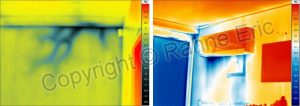
Detection of condensation and mold with thermography One common issue in residential buildings is condensation and, in most cases, the accompanying mold growth. The physical causes of condensation have been clarified earlier; here we focus on the structural, thermal insulation, or building operation reasons for condensation and mold growth. Possible causes of condensation:
Mold fungi can settle on surfaces where the following conditions persist for at least 3 to 7 days:
Based on these, it can be stated that whenever the presence of a thermal bridge can be demonstrated with thermographic tools, condensation also occurs if the temperature of the affected surface is lower than the dew point. To determine this, of course, the air temperature and relative humidity must also be measured. Today, there are many handheld instruments available at very favorable prices for this purpose, so this should not pose any particular difficulties.
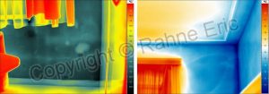
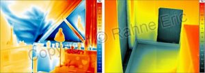
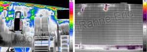
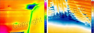
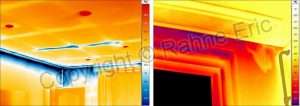
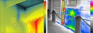
Most of the moisture generated in living spaces is supposed to be removed through ventilation. Due to the varying vapor diffusion properties of different building materials, there is also moisture equilibrium between the interior and exterior through them. In case of good design, when moisture diffuses into the building material, due to the resulting temperature decrease, either the dew point temperature does not occur in the material, or the material has the opportunity to dry out. Problems arise when the moisture diffusing into the material cannot dry outwards, or the vapor barrier layer in the cladding system is damaged, or simply missing. Even the smallest damage to the vapor barrier, such as a faulty joint between two foil layers, usually leads to local saturation of the affected material, mostly resulting in wetting of the insulation layer. Through the roof shown in the previous figure, approximately 1 g/m2 of water vapor escapes into the open air daily during winter, and nearly 4 g/m2 through the damaged vapor barrier belonging to the insulation system. This means that almost 4 million times more water vapor passes through the damaged layer compared to the vapor transmission of a flawless layer structure. The next thermal image example shows an industrial hall originally built as a warehouse, with intermediate insulation and corrugated sheet walls. The production installed inside generated a significant amount of water vapor, causing fog within the hall with a visibility of barely 10 m. The internally saturated air with water vapor then, in the absence of proper ventilation, did not escape through the non-airtight corrugated sheet joints of the external walls. The escaping air cooled down, and the water vapor in it condensed within the insulation material. The visible complete saturation was the result. The thermal image on the right side of the first row indicates condensation due to a thermal bridge near the pillar-roof structure of another industrial hall. Here, the flowing air behind the external cladding suddenly cools down, leading to condensation and soaking of the insulation. The thermal image on the left side of the second row illustrates a common mistake in attic construction. There is insulation and a vapor barrier, but during installation, the barrier was not properly secured to the wall or the next foil layer. Thus, moist indoor air escapes to the outside, and its cooling results in water vapor condensation, leading to wetting of the insulation and even to a similar amount of surface wetting as in the case of roof leakage. The situation is no different in the thermal image on the right side of the second row. Due to the incomplete airtight design of the attic cladding, the rising warm moist air, after cooling down, results in a puddle of condensed water.
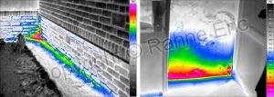
Recognition of capillary moisture and water ingress During thermographic inspection, the heat dissipation caused by evaporating moisture and the resulting temperature decrease due to the amount of evaporated heat can be detected. Of course, the measurement requires a thermal camera with particularly good thermal resolution. This method can identify the following fault phenomena:
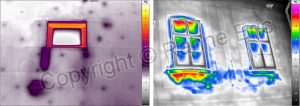
If capillary water absorption or external moisture exposure has led to complete saturation of the building element, we will observe temperature differences acting as thermal bridges due to the reduced insulation capacity of the affected structural element rather than evaporative heat. A good example of this is the thermal image on the right side of the first row, showing a completely wet wall section under a window due to frequent rain soaking. Internally, a particularly cold, damp wall can be found below the window.
Rahne Eric (PIM Ltd.) pim-kft.hu, termokamera.hu
The content of this publication is protected by copyright, and its (even partial) use, electronic or printed re-publication is only permitted with the indication of the source and the author's name, as well as the author's prior written permission. Violation of copyright (Copyright) will result in legal consequences.
Copyright © PIM Professzionális Ipari Méréstechnika Kft.
2026 | Minden jog fenntartva
Impresszum | Adatkezelés