


Eric Rahne, B.Sc. in Electrical Engineering, Level 3 Accredited Thermography Expert (PIM Ltd.)
From our series covering thermography, we have gained a lot of useful information: we have learned which device parameters are worth using for work, and we have also discovered a lot about the process of measurements. This time, we will focus on examining the areas around openings. These measurements need to be carried out by exploiting heat processes related to different weather conditions and times of day. The "trick" is to observe based on differences in heat capacity after daytime heating followed by a period without sunlight, or by revealing heat flow due to nighttime or winter cooling. In both cases, the differences in heat capacity and heat conduction between the materials to be inspected (sought) and their surroundings need to be utilized for the purpose of measurement and evaluation.
In case of proper heat flow, lintels made of steel, concrete, or even wood in the wall become visible using thermographic devices. (Steel and concrete become visible due to their high heat conductivity, while wood materials become visible due to their low heat conductivity and heat capacity.)
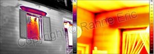
Different building materials in the wall (reconstructions, extensions, additions) with varying properties can be made visible under proper heat flow conditions. The different material needs to have a different heat capacity or heat conductivity compared to the surrounding materials. The necessary heat flow is generated by heating due to sunlight or can be created by cooling or heating. The principles of detection are the same as in the case of lintels. The detectability naturally depends on the temperature differences that can be created or already exist, as well as on the thermal resolution of the applied thermal camera. With a thermal resolution of 30 mK, even a hidden cellar door behind plasterboard in an unheated basement can be revealed.
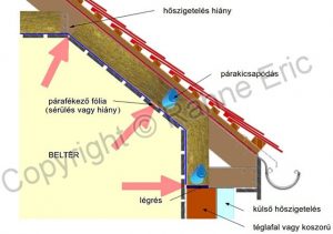
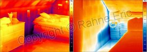
In the case of a correctly executed attic conversion, it also involves a building envelope with a double-shell structure. Therefore, a thermal image taken from the outside of the roof only reveals severe architectural flaws. Detecting insulation errors, missing or damaged vapor barriers or air barriers, and faulty non-airtight wall-roof connections is mostly possible from the inside.
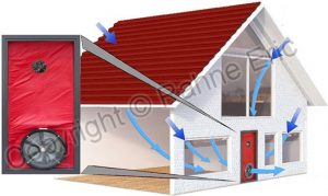
As mentioned in the previous examples, it has been noted that not only the physical absence or incorrect selection and placement of insulation materials can pose a problem, but also the airtightness of the building envelope. In modern, increasingly well-insulated buildings, the heat energy dissipated through the outer walls, roof, and windows due to their heat conductivity is significantly reduced. As a result, a growing proportion of energy loss occurs through air infiltration or ventilation-induced airflow, known as filtration heat energy loss. Of course, in hermetically sealed buildings, this type of energy flow would not occur. However, in such a case, the indoor environment would be unsuitable for living, as it would not provide us with the appropriate air quality due to oxygen deficiency, high CO2 content, and high humidity from breathing, cooking, washing, bathing, and plants. Ensuring the proper quality of indoor air in residential buildings requires continuous air exchange, the intensity of which naturally depends on the number of occupants and the nature of the building or room use. Several slightly different standards or architectural regulations in each country address the necessary level of air exchange, with the usual unit being the hourly air exchange rate. A typical value is n = 0.8 h-1, meaning that 80% of the total volume of indoor air is exchanged in one hour. Under certain circumstances, such as with automatic or mechanical ventilation, air exchange rates of 0.4 to 0.6 h-1 can be sufficient. (Note: for kitchens and bathrooms, an average flow rate of 45 m3/h is typically considered.)
Since the amount of air permeation depends on wind conditions, as well as the prevailing air pressure and possible chimney effect in the building, a method that eliminates these effects must be used to check and quantify airtightness. The examination is generally carried out using the so-called Blower-Door test. A fan blowing into the external space temporarily installed in one of the openings reduces the internal air pressure by 50 Pa compared to the external pressure. As a result, air flows in from the unsealed areas from the outside. The quantity of air delivered by the fan is proportional to the extent of the building envelope's airtightness.
The air exchange rate is then determined according to ISO 9972 based on the averaging of air flows in the pressurization and depressurization procedures:

from this:

where: V+50 ... quantity of air pressed by the fan [m3/h] at a pressure difference of +50 Pa V-50 ... quantity of air blown out by the fan [m3/h] at a pressure difference of -50 Pa V50 ... average airflow measured at a pressure difference of 50 Pa [m3/h] VL ... total net volume of the interior [m3] n50 ... air exchange rate referred to a 50 Pa pressure difference [h-1] When applying the Blower-Door procedure in the winter exhaust mode, due to the low air pressure created in the building, cold external air flows in through unsealed areas, cracks, and gaps. Although we cannot see the cold air with a thermal camera, the cooled building elements due to the cold air from the heated building can be well detected with thermographic tools. Examples of these are:
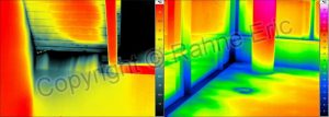
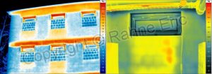
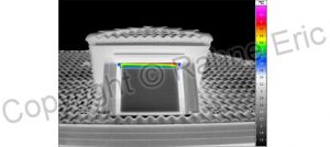
Doors, windows, and their installation play a significant role in the formation of thermal bridges, airtightness, and indirectly in the development of condensation and mold. Many of the problems related to doors and windows can be detected through thermographic surveys. However, it is important to be aware of the physical and metrological limitations when selecting the appropriate measurement conditions. Nevertheless, not everything can be measured. For example, do not attempt to determine the U-value of window panes through thermographic measurements in outdoor conditions. With a thermal camera of sufficient geometric resolution, the heating visible on the windows from the outside can detect not only poor sealing of the doors and windows but also the thermal bridge connection of the windows or air leakage from inadequate glass sealing, and these can be distinguished from each other. However, it is desirable to support the detected errors with internal images whenever possible. It would be quite challenging for larger buildings to individually examine each door and window in this way. Therefore, for larger buildings, it is advisable to first survey from the outside to identify critical or seemingly most critical doors and windows, or to determine if there is a common type of error present everywhere. Subsequently, the selected doors and windows should be thoroughly examined from inside the building. This should be done randomly, even if no suspicious heat effects are noticed from the outside! Concealed gaps or thermal bridges that are not visible from the outside can easily occur and may cause significant damage inside. However, do not assume improper windows or poor installations everywhere. Not every temperature difference indicates a fault. Do not forget the heat flows related to natural air movement. A good example is the heat effect visible in the thermal image at the bottom of the blind box, which is created due to the warmer air rising on the window pane. This is an unavoidable physical phenomenon, and at the temperatures seen here, it does not indicate any faults. To be continued!
Rahne Eric (PIM Ltd.) pim-kft.hu, termokamera.hu
The content of this publication is protected by copyright. Any (partial) use, electronic or printed re-publication is only permitted with the indication of the source and the author's name, and with the author's prior written permission. Violation of copyright (Copyright) will have legal consequences.
Copyright © PIM Professzionális Ipari Méréstechnika Kft.
2026 | Minden jog fenntartva
Impresszum | Adatkezelés